


Page 16
506728−01
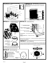
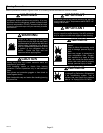
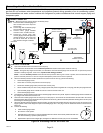
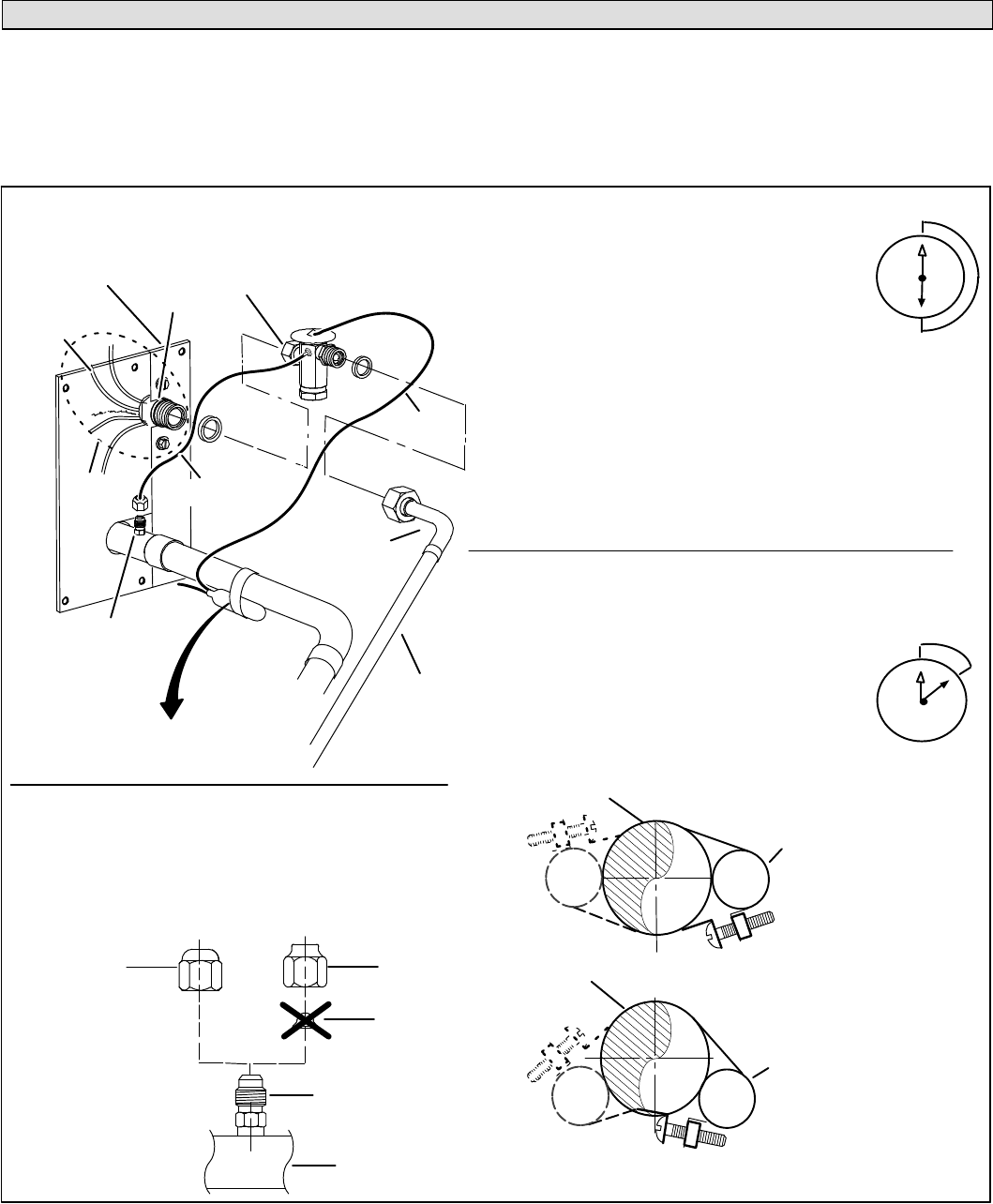
Installing New Indoor Metering Device
This outdoor unit is designed for use in HFC−410A systems that use a check / expansion valve metering device (purchased
separately) at the indoor coil.
See the Lennox XP14 Engineering Handbook for approved check / expansion valve kit match−ups. The check / expansion
valve device can be installed either internal or external to the indoor coil. In applications where an uncased coil is being
installed in a field−provided plenum, install the check / expansion valve in a manner that will provide access for field servicing
of the check / expansion valve (see figure 12).
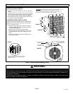
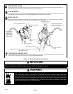
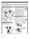
A Attach the vapor line sensing bulb in the proper
orientation as illustrated to the right using the clamp and
screws provided.
NOTE Ċ Confirm proper thermal contact between vapor line
and expansion bulb before insulating the sensing bulb once
installed.
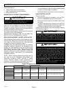
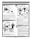
B Connect the equalizer line from the check / expansion
valve to the equalizer vapor port on the vapor line. Finger
tighten the flare nut plus 1/8 turn (7 ft−lbs) as illustrated
below.
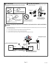
TWO PIECE
PATCH PLATE
(UNCASED
COIL ONLY)
VAPOR
LINE
LIQUID LINE
ORIFICE
HOUSING
DISTRIBUTOR
TUBES
LIQUID LINE
MALE EQUALIZER LINE
FITTING (SEE
EQUALIZER LINE
INSTALLATION FOR
FURTHER DETAILS)
SENSING
LINE
EQUALIZER
LINE
CHECK /
EXPANSION
VALVE
TEFLON
®
RING
(Uncased Coil Shown)
Sensing bulb insulation is
required if mounted external to
the coil casing.
STUB
END
TEFLON
®
RING
LIQUID LINE
ASSEMBLY WITH
BRASS NUT
DISTRIBUTOR
ASSEMBLY
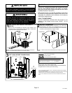
A Remove the field−provided fitting that temporarily
reconnected the liquid line to the indoor unit’s distributor
assembly.
B Install one of the provided Teflon
®
rings around the
stubbed end of the check / expansion valve and lightly
lubricate the connector threads and expose surface of
the Teflon
®
ring with refrigerant oil.
C Attach the stubbed end of the expansion valve to the
liquid line orifice housing. Finger tighten and use an
appropriately sized wrench to turn an additional 1/2 turn
clockwise as illustrated in the figure above, or 20 ft−lb.
D Place the remaining Teflon
®
washer around the other
end of the check / expansion valve. Lightly lubricate
connector threads and expose surface of the Teflon
®
ring with refrigerant oil.
E Attach the liquid line assembly to the check / expansion
valve. Finger tighten and use an appropriately sized
wrench to turn an additional 1/2 turn clockwise as
illustrated in the figure above or 20 ft−lb.
ON 7/8" AND LARGER LINES,
MOUNT SENSING BULB AT
EITHER THE 4 OR 8 O’CLOCK
POSITION. NEVER MOUNT ON
BOTTOM OF LINE.
12
ON LINES SMALLER THAN
7/8", MOUNT SENSING
BULB AT EITHER THE 3 OR
9 O’CLOCK POSITION.
12
BULB
VAPOR LINE
VAPOR LINE
NOTE Ċ NEVER MOUNT ON BOTTOM OF LINE.
BULB
BULB
BULB
VAPOR LINE
FLARE NUT
COPPER FLARE
SEAL BONNET
MALE BRASS EQUALIZER
LINE FITTING
FLARE SEAL CAP
OR
1
2
3
4
5
6
7
8
9
10
11
12
1/2 Turn
SENSING BULB INSTALLATION
EQUALIZER LINE INSTALLATION
1
2
3
4
5
6
7
8
9
10
11
12
1/8 Turn
Remove and discard either the flare seal cap or flare nut with
copper flare seal bonnet from the equalizer line port on the vapor
line as illustrated in the figure to the right.
INDOOR EXPANSION VALVE INSTALLATION
Figure 12. Installing Indoor Check / Expansion Valve