


Page 3
Installation (continued)
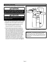
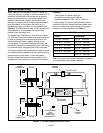
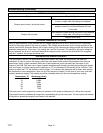
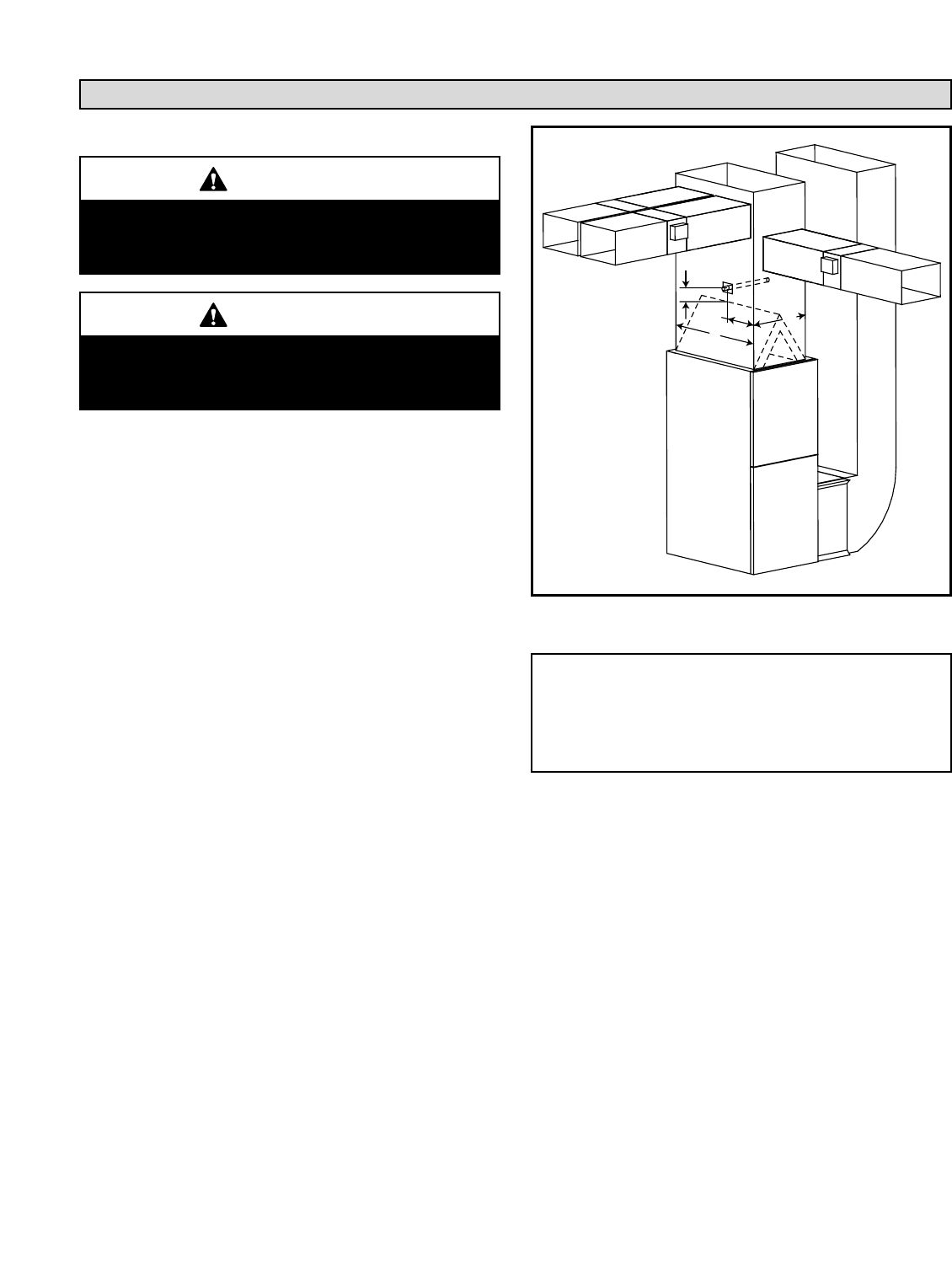
FIGURE 3 – DISCHARGE AIR SENSOR LOCATION
15"
D/3
W
D
FRONT
IMPORTANT: The discharge air sensor is required.
If a short or open circuit is detected between the
Plenum Sensor terminals, the control panel will only
respond to Zone 1 and the dampers will stay in the
open position.
4. Install and Wire the Discharge Air Temperature Sensor
The tip of the sensor must be located in a region of fully
mixed supply of air before the take-offs (not in a dead
air space) in order for the system to work correctly.
a. Wire discharge air temperature probe to control
panel using thermostat wire. Note that the
temperature sensor is not polarity sensitive.
b. Be sure that the tip of the sensor is located at
least 15 inches downstream from the leaving air
side of the evaporator in the discharge plenum,
and 1/3 of the depth (D/3) of the plenum (D) from
the front of the plenum (the front is the side with
the furnace or CB access doors), and centered
side to side. Move the adjustable bracket along
the length of the discharge air sensor to achieve
proper sensor tip location (tip of sensor to be
located at W ÷ 2). The sensor can be inserted
from any side of the plenum, as long as the tip of
the sensor is in the correct position. See Figure 3.
CAUTION
As with any mechanical equipment, personal injury
can result from contact with sharp sheet metal
edges. Be careful when you handle this equipment.
CAUTION
Before attempting to perform any service or
maintenance, turn the electrical power to unit OFF
at disconnect switch.