


506920−01 09/12
Page 60
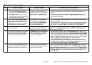
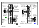
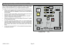
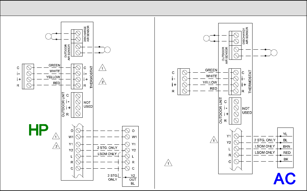
Wiring Diagrams
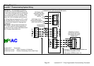
icomfortt Communicating Indoor/non−Communicating Outdoor System Wiring
icomfort Wi-Fit
Thermostat
icomfort by Lennoxt Air
Handler
Standard Outdoor Heat
Pump
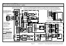
STANDARD
OUTDOOR HEAT
PUMP UNIT − 1
OR 2 STAGE
icomfort by Lennoxt AIR HANDLER (AHC)
icomfort
Wi-Fit
THERMOSTAT
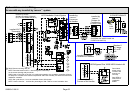
icomfort by Lennox
t FURNACE (IFC) OR AIR HANDLER (AHC)
icomfort
Wi-Fit
THERMOSTAT
STANDARD
OUTDOOR AIR
CONDITIONING
UNIT − 1 OR 2
STAGE
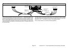
icomfort
Wi-Fit Thermostat
icomfort by Lennoxt Indoor Furnace or Air Handler
Standard Outdoor Condensing Unit
OPTIONAL OUT-
DOOR AIR SENSOR
(SEE OAS NOTE
Page 59)
OPTIONAL DIS-
CHARGE AIR SEN-
SOR (SEE DAS
NOTE Page 59)
OPTIONAL OUT-
DOOR AIR SENSOR
(SEE OAS NOTE
Page 59)
OPTIONAL DIS-
CHARGE AIR SEN-
SOR (SEE DAS
NOTE Page 59)
Maximum total
length of all connec-
tions on the RSBus
is limited to 1500ft.
Wire gauge of
RSBus wire is 18.
Maximum total
length of all connec-
tions on the RSBus
is limited to 1500ft.
Wire gauge of
RSBus wire is 18.
RSBus
RSBus
Setup Notes:
Cut Y1−Y2 Onboard Link
For 2−stage Outdoor
Units
Cut R−O Onboard Link
For Outdoor Heat Pump
Units
Setup Note:
Cut Y1−Y2 Onboard
Link For 2−stage
Outdoor Units