


SUPPLY AIR OUTLET
ADHESIVE BACKED FOAM TAPE
REAR-MOST BLOWER _'_
DECK HOLE
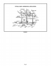
TYPICAL GHR26 INSTALLATION
(LEFT SIDE DISCHARGE ONLY - INSTALLED POSITION SHOWN)
S EXISTING REAR-MOST
CABINET SCREW
I
ADHESIVE BACKED FOAM TAPE
CONTROL ACCESS
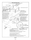
SUPPLY AIR TRANSITION
INSTALLATION -
(identify transition by its !7" x 20-3/8"
432mm x 518mm) plenum connection
size)
1 - Apply foam tape as shown.
2 -Align transition holes with the
three rear-most cabinet holes.
Return air transition holes will
not align in this position.)
Cabinet extends 2-3/8 inches
beyond transition at front.)
3 - Secure transition to cabinet
with existing screws. In re-
maining hole use self-drilling
self-tapping screw.
DRAIN LINE ROUTING HOLE
/
I
I
I
I
BRACE
HOLE"A"
FRONT BASE RAIL SET
RETURN AIR INLET
BLOWER ACCESS PANEL
DRAIN LINE ROUTING HOLE
REAR BASE RAIL SET
RETURN AIR TRANSITION INSTALLATION -
(identify transition by its 19-1/8" x 24"
(486mm x 619mm) plenum connection
size)
1 - Apply foam tape as shown.
2 - Align transition holes with three
the rear-most cabinet holes.
(Supply air transition holes will
not align in this position)
(Cabinet extends 2-3/8 inches
beyond transition at front.)
3 - Secure transition to cabinet
with existing screws. In remaining hole
use self-drilling self4apping screw.
SECURING SCREWS
SECURING
SCREWS
VIEW A
_" DETAIL B AIR TRANSITION
BASE RAILS INSTALLATION
A - Assemble rails: BASE RAIL TO TRANSITION JOINT
1 - Orient two rails used to form front rail set as shown in view A.
(Position drain line routing hole as shown.)
2 - Repeat for rear rail set.
3 - Position brace between front and rear rail sets as shown in main figure.
4 - Attach brace to rail sets with the four screws provided.
B - Attach rail assemb]y to transitions and unit:
1 - Remove rear-most blower deck screw.
2 - Align rear rail hole "A'as shown in main figure
with rear most blower deck hole.
3 - Secure rear rail set to unit and transitions. (See main figure and detail B)
4 - Repeat for front rail set using third blower deck hole from rear.
FIGURE 2
Page 4