


Note - Installation must conform with these
instructions and the installation instructions
packaged with the GHR26 furnace.
Note - The overall dimensions of the GHR26 and the
awkwardness of handling the GHR26 are increased
once transitions are installed.
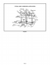
A - Return Air Transition installation.
Refer to figure 2,
1 - Lay GHR26 unit on its back (exposed internal parts
facing up), (Figure 2 shows installed position.)
2 - Remove the three rear-most cabinet screws at
return air inlet (3 each side),
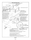
3 - Cut two strips from roll of adhesive-backed foam
tape (provided) to fit two cabinet sides as shown
in figure. Apply to cabinet sides.
4 - Install transition as shown.
5-Install filter as shown in GHR26 installation
instructions. GHR26Q4!5-100 unit will accept
installation of GSR14Q4/5-80!100 unit filter.
GHR26-50 and -75 units require a field provided
14x25x1 filter.
B - Supply Air Transition Installation.
Refer to figure 2.
t - Remove the three rear-most cabinet screws at
supply air inlet (3 each side).
2 - Cut two strips from roll of adhesive-backed foam
tape (provided) to fit two cabinet sides as shown
in figure. Apply to cabinet sides.
3 - Install transition as shown.
C - Base Rails Installation,
Refer to figure 2
1 - Install base rails as shown in figure 2.
D - Unit Installation
1 - Align unit with existing supply air plenum (coil
cabinet in air conditioning applications) and
return air plenum, Make connections to unit.
2- Connect low voltage wiring as illustrated in
GHR26 installation instructions.
3-Connect high voltage wiring as outlined in
GHR26 installation instructions.
4-Connect gas piping as outlined in GHR26
installation instructions.
Consult local codes for flexible connector
installation restrictions on GHR26 furnace.
5- Connect venting as outlined in GHR26
installation instructions,
Note - Mufflers can not be used in GHR26
installation. Check existing venting for size
(diameter and length). It should meet the
specifications as outlined in GHR26 installation
instructions. If a concentric vent is used for
GHR26-100 unit, it must be identified as catalog
number 33K97.
6 - Connect heat exchanger condensate drain line as
outlined in GHR26 unit installation instructions.
Note - Coil drain line must not be connected to
heat exchanger condensate drain line. ff lines
were connected, debris from evaporator could
affect heat exchanger operation.
7 - Continue with Unit Start-up Section as outlined
in GHR26 installation instructions,
Note - See GHR26 installation instructions for heat
anticipation settings.
Page 3