


Page 23
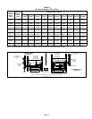
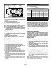
Integrated Control
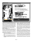
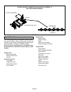
FIGURE 21
TWO−STAGE INTEGRATED CONTROL
THERMOSTAT CONNECTIONS (TB1)
1/4" QUICK CONNECT TERMINALS
DIP SWITCH FUNCTIONS
DIP
SWITCHES
DIAGNOSTIC
LEDs
ON−BOARD
LINKS
1= ERROR CODE RECALL
H= 24V HUMIDIFIER OUTPUT
L= LENNOX SYSTEM OPERATION MONITOR
SENSE = 120 VAC OUTPUT TO FLAME SENSER
NEUTRALS= 120 VAC NEUTRAL
PARK = DEAD TERMINAL FOR UNUSED BLOWER LEAD
HEAT LOW = 120 VAC OUTPUT TO CIRC BLWR −− LOW HT SPEED
HEAT HIGH/ COOL LOW = 120 VAC OUTPUT TO CIRC BLWR −−
HIGH HEAT AND LOW COOL SPEED
COOL HIGH = 120 VAC OUTPUT TO CIRC BLWR −− HIGH COOL SPEED
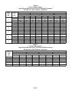
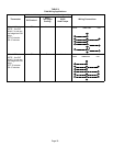
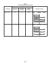
DIP SWITCH(ES) FUNCTION
1 −− 2 Stage T’stat Selects t/stat type (single or two−stage)
2 −− 2nd Stage Delay Second stage ON delay (single−stage t’stat)
3 & 4 −− Heat Off Delay Heating fan OFF delay
5 −− Cool Off Delay Cooling fan OFF delay
W915
W951
EL280DF units are equipped with a two−stage integrated
control. This control manages ignition timing and fan off
delays based on selections made using the control DIP
switches and jumpers. The control includes an internal
watchguard feature which automatically resets the ignition
control when it has been locked out. After one hour of con-
tinuous thermostat demand for heat, the watchguard will
break and remake thermostat demand to the furnace and
automatically reset the control to relight the furnace.
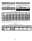
DIP Switch Settings
Switch 1 −− Thermostat Selection −− This unit may be used
with either a single−stage or two−stage thermostat. The
thermostat selection is made using a DIP switch which
must be properly positioned for the particular application.
The DIP switch is factory−positioned for use with a two−
stage thermostat. If a single−stage thermostat is to be used,
the DIP switch must be repositioned.
Select OFF" for two−stage heating operation con-
trolled by a two−stage heating thermostat (factory set-
ting);
b − Select ON" for two−stage heating operation con-
trolled by a single−stage heating thermostat. This set-
ting provides a timed delay before second−stage heat
is initiated.
Switch 2 −− Second Stage Delay (Used with Single−
Stage Thermostat Only) −− This switch is used to deter-
mine the second stage on delay when a single−stage ther-
mostat is being used. The switch is factory−set in the OFF
position, which provides a 10−minute delay before second−
stage heat is initiated. If the switch is toggled to the ON
position, it will provide a 15−minute delay before second−
stage heat is initiated. This switch is only activated when
the thermostat selector jumper is positioned for SINGLE−
stage thermostat use.
Switches 3 and 4 −− Heating Blower−Off Delay −− The
heating blower−on delay of 45 seconds is not adjustable.
The heating blower−off delay (time that the blower operates
after the heating demand has been satisfied) can be ad-
justed by moving switches 3 and 4 on the integrated con-
trol. The unit is shipped from the factory with a heating
blower−off delay of 90 seconds. The heating blower off
delay affects comfort and is adjustable to satisfy individual
applications. Adjust the blower off delay to achieve a sup-
ply air temperature between 90° and 110°F at the exact
moment that the blower is de−energized. Longer off delay