


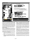

Page 18
Leak Check
After gas piping is completed, carefully check all piping
connections (factory− and field−installed) for gas leaks. Use
a leak detecting solution or other preferred means.
NOTE − If emergency shutoff is necessary, shut off the main
manual gas valve and disconnect the main power to the
furnace. The installer should properly label these devices.
CAUTION
Some soaps used for leak detection are corrosive to
certain metals. Carefully rinse piping thoroughly af-
ter leak test has been completed. Do not use
matches, candles, flame or other sources of ignition
to check for gas leaks.
The furnace must be isolated from the gas supply system
by closing its individual manual shut-off valve during any
pressure testing of the gas supply system at pressures
greater than or equal to 1/2 psig (3.48 kPa, 14 inches w.c.).
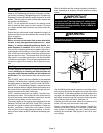
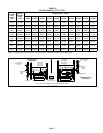
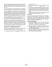
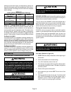
IMPORTANT
When testing pressure of gas lines, gas valve must
be disconnected and isolated. See figure 18. Gas
valves can be damaged if subjected to pressures
greater than 1/2 psig (3.48 kPa, 14 inches w.c.).
MANUAL MAIN
SHUT−OFF VALVE
WILL NOT HOLD
NORMAL TEST
PRESSURE
CAP
ISOLATE
GAS VALVE
FURNACE
FIGURE 18
1/8 NPT PLUG
Electrical
ELECTROSTATIC DISCHARGE (ESD)
Precautions and Procedures
CAUTION
Electrostatic discharge can affect elec-
tronic components. Take precautions to
neutralize electrostatic charge by
touching your hand and tools to metal
prior to handling the control.
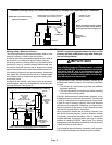
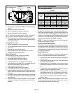
The unit is equipped with a field make−up box on the left
hand side of the cabinet. The make−up box may be moved
to the right side of the furnace to facilitate installation. If the
make−up box is moved to the right hand side, clip the wire
ties that bundle the wires together. Secure the excess wire
to the existing harness to protect it from damage.
INTERIOR MAKE−UP BOX INSTALLATION
(Right Side)
FIGURE 19
MAKE−UP
BOX
Cut the two wire ties to extend power wires for right side only
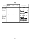
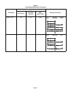
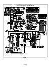
Refer to figure 20 for schematic wiring diagram and trou-
bleshooting and table 9 for field wiring.
The power supply wiring must meet Class I restrictions.
Protected by either a fuse or circuit breaker, select circuit
protection and wire size according to unit nameplate.
NOTE − Unit nameplate states maximum current draw.
Maximum over−current protection allowed is 15 AMP.
Holes are on both sides of the furnace cabinet to facilitate
wiring.
Install a separate (properly sized) disconnect switch near
the furnace so that power can be turned off for servicing.
Before connecting the thermostat, check to make sure the
wires will be long enough for servicing at a later date. Make
sure that thermostat wire is long enough to facilitate future
removal of blower for service.
Complete the wiring connections to the equipment. Use
18−gauge wire or larger that is suitable for Class II rating for
thermostat connections.
Electrically ground the unit according to local codes or, in
the absence of local codes, according to the current Na-
tional Electric Code (ANSI/NFPA No. 70). A green ground
wire is provided in the field make−up box.
NOTE − The EL280DF furnace contains electronic compo-
nents that are polarity sensitive. Make sure that the furnace
is wired correctly and is properly grounded.
Accessory Terminals
One line voltage EAC" 1/4" spade terminal is provided on
the furnace integrated control. See figure 21 for integrated
control configuration. This terminal is energized when the
indoor blower is operating. Any accessory rated up to one
amp can be connected to this terminal with the neutral leg