


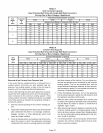
ralgasatallaltitudesis3.5"w.c.Manifoldpressurefor
allunitsfueledbyL.R/propanegasat allaltitudesis
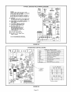
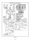
10.0"w,c.Seefigures27,28and29forthelocationof
themanifoldpressureadjustmentscrews,
NOTE - In Canada, certification for installations at eleva-
tions over 4500 feet (1372 m) is the jurisdiction of local au-
thorities.
Manifold pressure for all units fueled by natural gas at all
altitudes is 3.5" w,c, Manifold pressure for all units fueled
by L,R/propane gas at all altitudes is 10,0" w,c,
NOTE - A natural to L.R propane gas changeover kit is nec-
essary to convert this un#. L.R conversion kit 25W20 is
used with all units installed at altitudes up to 7,500 feet. L.P.
conversion kit 25W21 is used with all units installed at alti-
tudes from 7,501 to 10,000 feet above sea level. Refer to
the changeover kit installation instruction for the conver-
sion procedure.
NOTE - Units fueled by natural gas and installed at alti-
tudes of 7501-10,000 feet above sea level require instal-
lation of a high altitude orifice kit (59M17).
The combustion air pressure switches are factory-set and
require no adjustment, The existing unit pressure switch
must be replaced by pressure switch 56L32 for G50UH(X)
units installed at altitudes from 7,501 to 10,000 feet above
sea level,
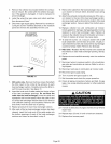
Primary and Secondary Limits
The primary limit is located on the heating compartment
vestibule panel. The secondary limits (if equipped) are lo-
cated in the blower compartment, attached to the back side
of the blower. These limits are factory set and require no
adjustment.
Flame Rollout Switches (Two)
These manually reset switches are located on (or inside of)
the burner box, If tripped, check for adequate combustion
air before resetting,
Pressure Switch
The pressure switch is located in the heating compartment
adjacent to the combustion air inducer. This switch checks
for proper combustion air inducer operation before allow-
ing ignition trial, The switch is factory-set and requires no
adjustment.
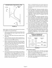
Temperature Rise
Place the unit into operation with a heating demand, After
supply and return air temperatures have stabilized, check
the temperature rise, If necessary, adjust the blower speed
to maintain the temperature rise within the range shown on
the unit nameplate, Increase the blower speed to decrease
the temperature, Decrease the blower speed to increase
the temperature rise, Failure to do adjust the temperature
rise may cause erratic limit operation,
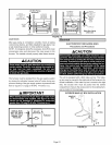
Fan Control
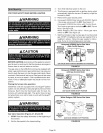
Heating Mode -- The fan on delay of 45 seconds is not ad-
justable. The fan offdelay (amount of time that the blower
operates after the heat demand has been satisfied) may
be adjusted by setting $1 switches 1and 2 located on the
SureLight ® control. The unit is shipped with a factory fan
off setting of 90 seconds, The fan off delay affects com-
fort and is adjustable to satisfy individual applications.
Adjust the fan off delay to achieve a supply air tempera-
ture between 90 °and 110°F at the exact moment that the
blower is de-energized. Longer offdelay settings provide
lower return air temperatures; shorter settings provide
higher return air temperatures. See figure 25.
Cooling Mode --The cooling mode fan off delay (amount
of time that the blower operates after the cooling demand
has been satisfied) may be adjusted by setting $1 switch
3 located on the SureLight ® control, In the off position,
the cooling fan off delay is 2 seconds. In the on position,
the cooling fan off delay is 45 seconds, See figure 25,
Thermostat Heat Anticipation
Set the heat anticipator setting (if adjustable) according to
the amp draw listed on the wiring diagram that is attached
to the unit.
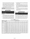
Electrical
1 - Check all wiring for loose connections,
2 - Check for the correct voltage at the furnace (furnace
operating).
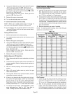
3 - Check amp-draw on the blower motor.
Motor Nameplate Actual
NOTE - Do not secure the electrical conduit directly to the
air ducts or structure.
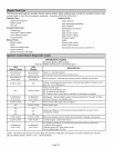
Blower Speeds
NOTE - CFM readings are taken external to unit with a dry
evaporator coil and without accessories.
1 - Turn off electrical power to furnace,
2 - Remove blower access panel.
3 - Disconnect existing speed tap at control board speed
terminal.
NOTE - Termination of any unused motor leads must be
insulated.
4 - Refer to blower speed selection chart on unit wiring dia-
gram for desired heating or cooling speed.
5- Connect selected speed tap at control board speed
terminal.
6 - Resecure blower access panel.
7 - Turn on electrical power to furnace,
Electronic Ignition
The SureLight @integrated control has an added feature of
an internal Watchguard control, The feature serves as an
automatic reset device for ignition control lockout caused
by ignition failure, After one hour of continuous thermostat
demand for heat, the Watchguard will break and remake
thermostat demand to the furnace and automatically reset
the control to begin the ignition sequence,
Page 27