


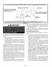
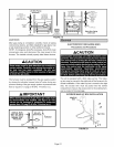

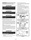
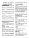
INTERIORMAKE-UP BOX INSTALLATION
MAKE-UP
Left side / BOX
_ °
FIGURE 22
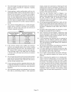
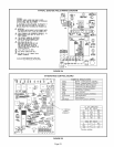
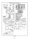
Refer to figure 24 for field wiring and figure 26 for schematic
wiring diagram and troubleshooting.
1 - Select circuit protection and wire size according to the
unit nameplate. The power supply wiring must meet
Class I restrictions,
2 - Holes are on both sides of the furnace cabinet to facili-
tate wiring,
3 - Install a separate disconnect switch (protected by ei-
ther fuse or circuit breaker) near the furnace so that
power can be turned off for servicing,
4 - Before connecting the thermostat or the power wiring,
check to make sure the wires will be long enough for
servicing at a later date, Remove the blower access
panel to check the length of the wire,
5- Complete the wiring connections to the equipment.
Use the provided unit wiring diagram and the field wir-
ing diagram shown in figure 24, Use 18-gauge wire or
larger that is suitable for Class II rating for thermostat
connections,
6 - Electrically ground the unit according to local codes or,
in the absence of local codes, according to the current
National Electric Code (ANSI/NFPA No, 70) for the
USA and current Canadian Electric Code part 1 (CSA
standard C22.1) for Canada. A green ground wire is
provided in the field make-up box,
NOTE - The G5OUH(X) furnace contains electronic
components that are polarity sensitive. Make sure
that the furnace is wired correctly and is properly
grounded.
7 - One line voltage "EAC" terminal is provided on the fur-
nace control board. Any electronic air cleaner rated up
to one amp can be connected to this terminal with the
neutral leg of the circuit being connected to any of the
"NEUTRAL" terminals. See figure 25 for control board
configuration. This terminal is energized when the
blower is operating,
8 - One line voltage "HUM" terminal is provided on the fur-
nace control board, A humidifier rated up to one amp
can be connected to this terminal with the neutral leg
of the circuit being connected to any of the "NEUTRAL"
terminals. See figure 25 for control board configura-
tion. This terminal is energized in the heating mode
whenever the combustion air inducer is operating.
9 - One 24 volt terminal "24V HUM" is provided on the fur-
nace control board. A humidifier rated up to 0.5 amp
can be connected to this terminal with the common leg
of the circuit being connected to the "C" terminal d the
thermostat terminal block located on the control board.
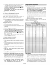
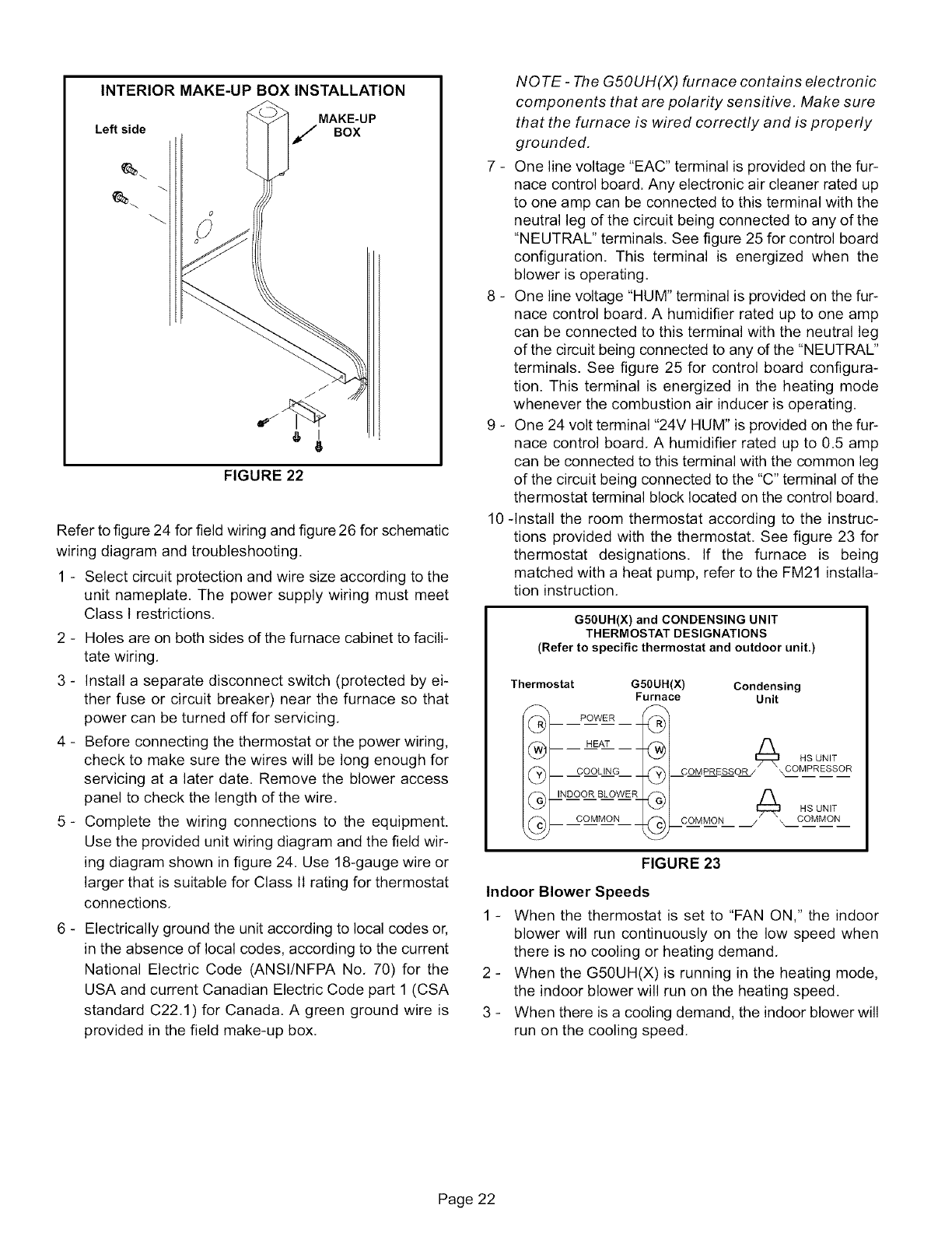
10-Install the room thermostat according to the instruc-
tions provided with the thermostat. See figure 23 for
thermostat designations. If the furnace is being
matched with a heat pump, refer to the FM21 installa-
tion instruction.
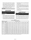
G50UH(X) and CONDENSING UNIT
THERMOSTAT DESIGNATIONS
(Refer to specific thermostat and outdoor unit.)
Thermostat G50UH(X) Condensing
Furnace Unit
PowER
@1 HsuN,T
FIGURE 23
Indoor Blower Speeds
1 - When the thermostat is set to "FAN ON," the indoor
blower will run continuously on the low speed when
there is no cooling or heating demand,
2 - When the G50UH(X)is running in the heating mode,
the indoor blower will run on the heating speed.
3 - When there is a cooling demand, the indoor blower will
run on the cooling speed,
Page 22