


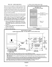
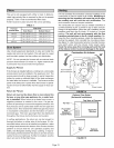
Thisunitisnotequippedwithafilteror rack.A field-pro-
videdhigh-velocityfilterisrequiredfortheunittooperate
properly.Table1listsrecommendedfiltersizes.
Afiltermustbeinplaceanytimetheunitisoperating.
Furnace
Cabinet Size
14-1/2"
17-112"
21"
24-1/2"
TABLE 1
Filter Size
Side Return
16X25X 1 (1)
16X25X 1 (1)
16X25X 1 (1)
16 X 25 X 1 (2)
Bottom Return
14X25X1 (1)
16X25X1 (1)
20X25X 1 (1)
24X25X 1 (1)
Use industry-approved standards to size and install the
supply and return air duct system. This will result in a quiet
and low-static system that has uniform air distribution.
NOTE - Do not operate the furnace with an external static
pressure that exceeds 0,5 inches w,c, Higher external stat-
ic pressures may cause erratic limit operation,
Supply Air Plenum
If the furnace is installed without a cooling coil, a removable
access panel must be installed in the supply air duct, The
access panel should be large enough to permit inspection
(either by smoke or reflected light) of the heat exchanger
for leaks after the furnace is installed, The furnace access
panel must always be in place when the furnace is operat-
ing and it must not allow leaks into the supply air duct sys-
tem,
Return Air Plenum
Return air must not be drawn from a room where this
furnace, or any other gas appliance (ie., a water heat-
er), is installed. When return air is drawn from a room, a
negative pressure is created in the room, If a gas ap-
pliance is operating in a room with negative pressure, the
flue products can be pulled back down the vent pipe and
into the room, This reverse flow of the flue gas may result
in incomplete combustion and the formation of carbon
monoxide gas. This toxic gas might then be distributed
throughout the house by the furnace duct system,
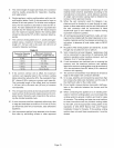
In upflow applications, the return air can be brought in
through the bottom or either side of the furnace. If a fur-
nace with bottom return air is installed on a platform, make
an airtight seal between the bottom of the furnace and the
platform to ensure that the unit operates properly and
safely, Use fiberglass sealing strips, caulking, or equiva-
lent sealing method between the plenum and the furnace
cabinet to ensure a tight seal, Ifa filter is installed, size the
return air duct to fit the filter frame.
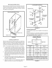
A 4-inch diameter flue transition is factory-installed on the
combustion air inducer outlet of all models. Modifying or
removing the flue transition will cause the unit to oper-
ate unsafely and will void the unit certification. The
vent connector does not require insulation.
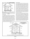
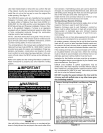
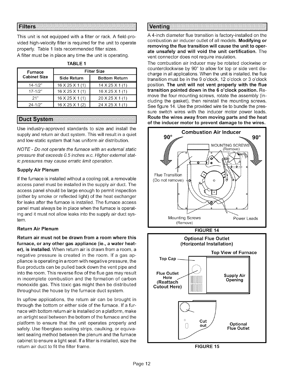
The combustion air inducer may be rotated clockwise or
counterclockwise by 90° to allow for top or side vent dis-
charge in all applications. When the unit is installed, the flue
transition must be in the 9 o'clock, 12 o'clock or 3 o'clock
position. The unit will not vent properly with the flue
transition pointed down in the 6 o'clock position. Re-
move the four mounting screws, rotate the assembly (in-
cluding the gasket), then reinstall the mounting screws.
See figure 14. Use the provided wire tie to bundle the pres-
sure switch wires with the inducer motor power leads.
Route the wires away from moving parts and the heat
of the inducer motor to prevent damage to the wires.
Combustion Air Inducer
Flue Transition
(Do not remove)
Mounting Screws
(Remove)
FIGURE 14
Power Leads
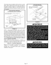
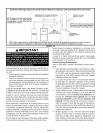
Optional Flue Outlet
(Horizontal Installation)
Top View of Furnace
Top Cap ----__ _
Flue Outlet _<_J
Hole /
(Reattach II 111
Cutout Here)
Supply Air
Opening
Optional
Flue Outlet
FIGURE 15
Page 12