


Nominal
Iron Pipe Size
-InchesImm)
t/4
(635)
3/8
(6,53)
(127)
314
(19.05)
1
(254)
1-1/4
(31.75)
Io1/2
(381)
2
(5O.8)
2-112
(83.5)
3
(76.2)
4
(101.6)
NOTE - Capacity j
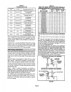
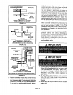
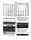
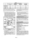
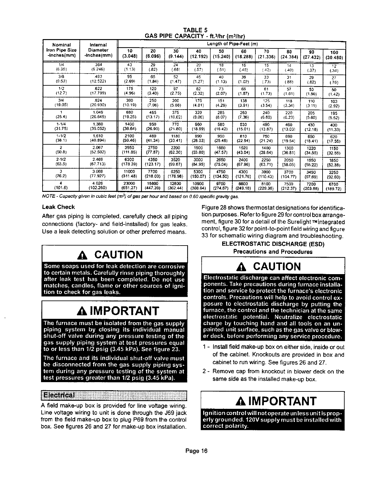
TABLE 5
GAS PIPE CAPACITY - ft.3/hr Im31hrl
Internal Length of Pipe-Feet (m)
Diameter 10 20 30 40 50 60 70 80 90 100
.InchesImm) (3.048) (6.096) (9.144) (12.192) 115.2401 (18.288) (21.336) (24.384) (27.432 (30.480)
364 43 29 24 29 18 18 15 14 19 12
(9 246) (1 13) (.82) (68) (.57) (81) (45) ( 401 (40} (3?) (.34)
493 95 65 52 45 40 36 33 31 29 27
(12.5221 (269) (1.84) (1 47) (127) (113) (1.02) (73) (88) (.82) (75)
622 175 120 97 82 73 66 61 57 53 50
(17.799) (496) (340) (2.75) (232) (2.07) (1.87) (173) (101) (1.50) (142)
.824 360 250 200 176 161 138 125 118 110 103
(20.930) (10.19) {706) (566) (4.81) (4.28) (3.91) (3 54) (3.34) (3 11) (292)
1049 680 468 379 320 288 260 240 220 208 !95
(26.645) (19,25) (13.17) (10,62) (9,06) (807) (7.36) (6 90) (6.23) (580) (6.62)
1.380 1400 960 770 660 580 630 490 460 430 400
(35.052) (39.64) (26.90) (21.80) (18,69) (1642) (15.01) (13.67) (13.031 (1218) (11.33)
1.610 21 O0 466 1180 990 900 810 750 690 650 620
(40.894) (59.46) (41.34) (3341) (2803) (2548) (22.94) (2124) (19.54) (1841) (17,56)
2.0_7 3950 2750 2200 1906 1680 1520 1400 1300 1220 1150
(52.502) (111.85) (77,87) (62.30) (5380) (47.57) (43.041 (3964) (36.81) (34.58) (32.56)
2469 6300 4350 9520 3000 2650 2400 2250 2050 1950 1880
(67 713) (17839) (12317) (9967) (84.95) (75.04) (67.96) (63.71) (58,05) (55.22) (52.38)
3068 11000 7700 6250 5300 4750 4300 3900 3700 3450 3250
(77.927) (31148) (218.03) (17698) (150.07) (134.50) (121,76) (110.43) (104.77) (97,69) (92.03)
4 026 23000 15800 12800 10900 9700 8800 St00 7500 7200 6700
(102.260) (651.27) (447.39) (362 44) (308.64) (274.67) (249.t8) (229.99) (212.37) (203.88) (189.72)
'iven in cubsc feet (m 3) o f gas per hour and based on O.60 specific gravity gas.
Leak Check
After gas piping is completed, carefully check all piping
connections (factory- and field-installed) for gas leaks.
Use a leak detecting solution or other preferred means.
CAUTION
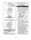
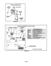
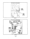
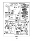
Figu re 28 shows thermostat designations for identifica-
tion purposes. Refer to figure 29 for control box arra nge-
ment, figure 30 for a detail of the Surelight _integrated
control, figure 32 for point-to-point field wiring and figure
33 for schematic wiring diagram and troubleshooting,
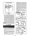
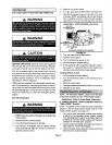
ELECTROSTATIC DISCHARGE (ESD)
Precautions and Procedures
A, IMPORTANT 1
iii::i:: i.................j
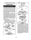
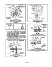
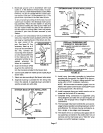
A field make-up box is provided for line voltage wiring.
Line voltage wiring to unit is done through the J69 jack
from the field make-up box to plug P69 from the control
box. See figures26 and 27 for make-up box installation.
1 - Install field make-up box on either side,inside orout
of the cabinet. Knockouts are provided in box and
cabinet to run wiring. See figures 26 and 27.
2 - Remove cap from knockout in blower deck on the
same side as the installed make-up box.
A IMPORTANT
Page 16