


{
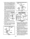
NOTE - Exhaust piping should be checked carefully
to make sure there are no sags or low spots.
NOTE - Exhaust piping must be Insulated wffh 1/2 inch
(13 ram) Armaflex or equivalent when nJn through un-
heated space. Do not leave any area of exhaust pipe
open to outside air. extenor exhaust must be insulated
wrth 1/2 inch (13 ram) Armaflex or equivalent.
Zl, CAUTION
I
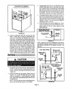
CAUTION
Removal of Unit from Common Venting System
In the event that an existing furnace is removed from a
venting system commonly run with separate gas ap-
pliances, the venting system may be too largeto property
vent the remaining attached appliances. The following
test should be conducted while all appliances (beth in op-
eration and those not in operation) are connected to the
common venting system.If the venting system has been
installed improperly, corrections must be made as out-
lined in the previous section.
1 - Seal any unused openings in the common venting
system.
2 - Visually inspect the venting system for proper size
and horizontal pitchand determinethere is noblock-
age or restdction,leakage, corrosionor other defi-
ciencies whichcouldcause an unsafe condition.
3 - To the extent that it is practical, close all building
doors andwindows,and alldoorsbetweenthe space
in which the appliancesremainingconnectedto the
common venting system are located and other
spaces of the building. Turn on clothes dryers and
any appliances not connectedto the common vent-
ing system. Turn on any exhaust fans, suchas range
hoods and bathroom exhausts, so they willoperate
at maximum speed. Do not operate a summer ex-
haust fan. Close fireplace dampers.
4 - Follow the lightinginstructions. Place the appliance
being inspected in operation. Adjust thermostat so
appliance will operate continuously.
5 - Test for spillage at the draft hood relief openingafter
5 minutes of main burner operation. Usethe flame of
match or candle, or smoke from a cigarette or cigar,
or a draftgauge.
6- After determining that each appliance remaining
connected to the common venting system properly
vents when tested as indicated in step 3, return
doors, windows, exhaust fans, fireplace dampers
and any other gas-burning appliance to their pre-
vious condition of use.
7 - If improper venting is observed dudng any of the
above tests, the common venting system must be
corrected. The common venting system shouldbe
resized to approach the minimum size as deter-
mined by using the appropriate tables in appendixG
in the current standards of the National Fuel Gas
Code ANSI Z223-1 in the USA, and the appropriate
Category 1 Natural Gas appliances venting sizing
tables in the current standard of the CAN/
CGA-B149.1 in the Natural Gas InstalLationCode in
Canada.
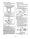
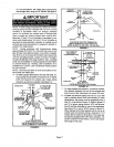
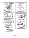
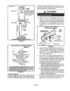
Intake and Exhaust Piping Terminations
Intake and exhaustpipesmay be routedeitherhorizontal-
lythrough an outsidewall or verticallythroughthe roof.In
attic or closet instaUations,vertical terminationthrough
the roof is preferred. Figures 8 through20 show typical
terminations.
1 - Use recommended piping materials for both intake
and exhaust piping.
2 - Secure all joints, includingdrain leg, gas tightusing
approved cement.
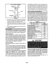
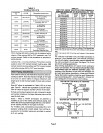
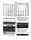
3 - Pipingdiametersshouldbe determinedaccordingto
length of pipe run.See table 4. Locate intakepiping
upwind (prevailing wind) from exhaust piping. To
avoid recirculation of exhaust gas on roof termina-
tions, end of exhaust pipe must be higher than intake
pipe.
Exhaust and intake exits must be in same pressure
zone. Do not exit one through the roof and one on the
side. Also, do not exit the intake on one sideand the
exhaust on another side of the house or structure.
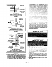
4 - intake and exhaust pipes should be placed as close
together as possible at termination end (refer to il-
lustrations). Maximum separation is 3 inches (76
ram) on roof terminations and 6 inches (152 ram)on
sidewall terminations.
5 - Exhaustpipingmust terminate straightout or up as
shown, tn rooftopapplications,a 2 inchX 1-1/2 inch
reducer for 2 inch venting,3 inch x 2 inch reducerfor
3 inch venting must be used on the exhaust piping at
the point where it exits the structure to improve the
velocity of exhaust away from the intakepiping.
Page 10