


Page 33
9 − Is the unit ignition system in lock out? If the unit locks out
again, call the service technician to inspect the unit for
blockages.
10 − Is pressure switch closed? Obstructed flue will cause
unit to shut off at pressure switch. Check flue and outlet
for blockages.
11 − Are flame rollout switches tripped? If flame rollout
switches are tripped, call the service technician for in-
spection.
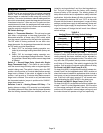
Gas Pressure Adjustment
Gas Flow (Approximate)
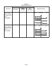
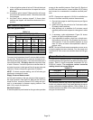
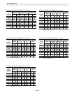
TABLE 12
GAS METER CLOCKING CHART
EL280UH
Unit
Seconds for One Revolution
Natural LP
1 cu ft
Dial
2 cu ft
Dial
1 cu ft
Dial
2 cu ft
DIAL
−045 80 160 200 400
−070 55 110 136 272
−090 41 82 102 204
−110 33 66 82 164
−135 27 54 68 136
Natural−1000 btu/cu ft LP−2500 btu/cu ft
Furnace should operate at least 5 minutes before check-
ing gas flow. Determine time in seconds for two revolu-
tions of gas through the meter. (Two revolutions assures a
more accurate time.) Divide by two and compare to time
in table 12 below. If manifold pressure matches table 14
and rate is incorrect, check gas orifices for proper size and
restriction. Remove temporary gas meter if installed.
NOTE − To obtain accurate reading, shut off all other gas
appliances connected to meter.
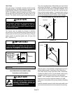
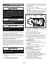
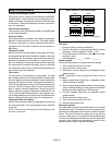
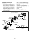
Supply Pressure Measurement
An inlet post located on the gas valve provides access to
the supply pressure. See figure 34. Back out the 3/32" hex
screw one turn, connect a piece of 5/16" tubing and con-
nect to a manometer to measure supply pressure. See
table 14 for supply line pressure.
Manifold Pressure
A manifold pressure post located on the gas valve provides
access to the manifold pressure. See figure 34. Back out
the 3/32 hex screw one turn, connect a piece of 5/16" tubing
and connect to a manometer to measure manifold pres-
sure.
NOTE − Pressure test adapter kit (10L34) is available from
Lennox to facilitate manifold pressure measurement.
1 − Connect test gauge to manifold pressure post (figure
34) gas valve.
2 − Ignite unit on high fire and let run for 5 minutes to allow
for steady state conditions.
3 − After allowing unit to stabilize for 5 minutes, record
manifold pressure and compare to value given in table
14.
4 − If necessary, make adjustments. Figure 34 shows
location of high fire adjustment screw.
5 − If an adjustment is made on high fire, re−check man-
ifold pressure on low fire. Do not adjust low fire man-
ifold pressure. If low fire manifold pressure is more
than 1/2" above or below value specified in table 14,
replace valve.
NOTE − Shut unit off and remove manometer as soon as an
accurate reading has been obtained. Turn the supply and
manifold 3/32" hex screw one revolution back into the gas
valve.
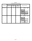
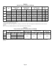
Proper Combustion
Furnace should operate minimum 15 minutes with correct
manifold pressure and gas flow rate before checking com-
bustion. Table 13 shows acceptable combustion for ALL
EL280UH models. The maximum carbon monoxide
reading should not exceed 50 ppm
TABLE 13
Firing Rate
CO
2
%
For
Nat
CO
2
%
For
L.P.
High Fire 6.8 − 7.4 7.5 − 9.0
Low Fire 4.2 − 5.7 5.0 − 6.0
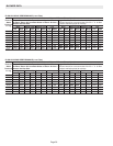
High Altitude
The manifold pressure may require adjustment and com-
bustion air pressure switch may need replacing to ensure
proper combustion at higher altitudes. Refer to table 14 for
manifold pressure and table 15 for pressure switch change
and gas conversion kits.