


8
NOTE: DIAGRAMS & ILLUSTRATIONS ARE NOT TO SCALE.
Facing &
Mantel -
Side View
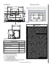
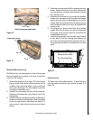
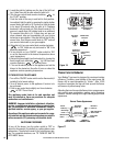
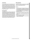
faCing and mantel ClearanCes
Note: Hearth protection to be min. 3/8” (10mm) thick non-
combustible or equivalent, with a k factor of .84.
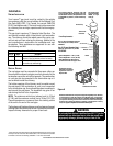
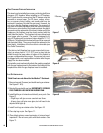
insert leveling
At each front and rear corner of the insert is an adjustable leg
provided to level the insert should the hearth of the fireplace
be uneven. To adjust the legs, loosen the two 5/32" allen head
screws, move the leg to the desired height, and then tighten
the screws. Repeat these steps for each adjusting leg.
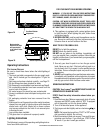
G 13”(330mm) 10”(254mm) 0”(0mm)
H 0”(0mm) 2”(21mm) 4”(102mm)
E
H
F
G
J
C
L
MANTEL
TRIM
Mantel
Trim
Hearth / Floor Protection
E = 31-1/2" (800mm) from Top Facing to Bottom of
Insert
F = 25-1/2” (648mm) from Center of Glass to Side Facing
or Side Wall
J = 39” (991mm) from 10.5” (267mm) Mantel to Bottom
of Insert
hearth proteCtion
G = Minimum Hearth Protection from Front of Insert*
H = Vertical Distance from Insert Bottom to Combustible
Material.
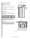
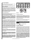
Clearances to Combustibles
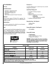
minimum ClearanCes to Combustibles
3"/76mm
3"/76mm
3"/76mm
1-1/2”
38mm
31-1/2”
800mm
33-1/2”
851mm
36-1/2”
927mm
39-1/2”
1003mm
ClearanCes
Figure 4
Figure 5