


12
NOTE: DIAGRAMS & ILLUSTRATIONS ARE NOT TO SCALE.
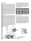
Gas Line Installation
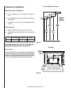
After leveling, position the insert in the fireplace - holding
it about six inches out from its final location.
Caution: Specific hearth requirements apply (see Clear-
ances to Combustibles).
The Medina™ gas insert must be connected to the gas line
in accordance with local codes and/or the National Fuel Gas
Code, ANSI Z223.1 (In Canada, the current CAN/CSA B149.1
installation code). The insert comes with an 8" nipple at-
tached to the supply side of the gas valve. After connecting
the gas line, all joints in the line and connections at the valve
should be checked for leaks with a gas leak test solution
before final positioning of the unit.
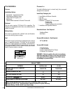
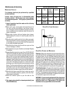
gas pressure requirements
A MAJOR CAUSE OF OPERATING PROBLEMS WITH GAS
APPLIANCES IS IMPROPER GAS PRESSURE!
The most important item to check during the initial
installation and the first thing to check when operating
problems occur is gas pressure! This appliance will
not function properly unless the required gas pressure
is supplied. See the table on this page for gas pressure
requirements.
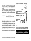
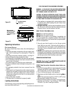
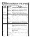
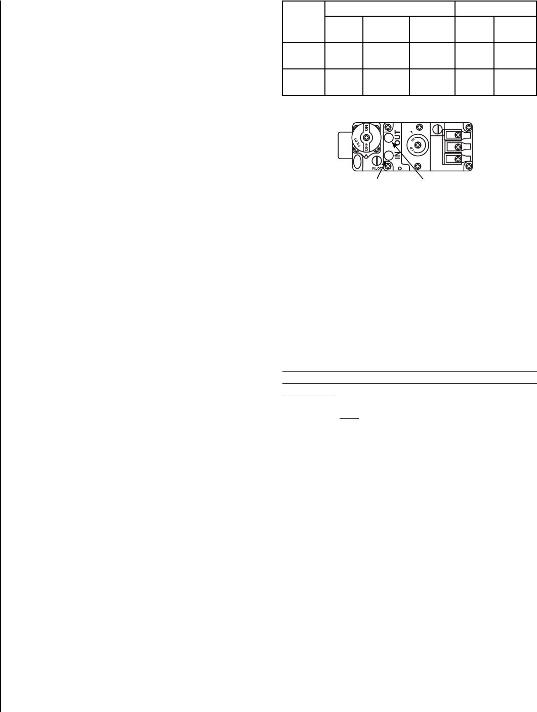
Two pressure taps are provided on the insert's valve to
check gas pressures. The taps are located to the right of
the on/off/pilot knob (see Figure 15). The bottom tap is the
inlet (supply) pressure side. To check inlet pressure (with
the insert burning), insert a small phillips screwdriver into
the tap and turn a half turn counter-clockwise. Cover the
tap with the line from a manometer and check the pressure.
Close tap gently but securely after completing the check.
The manifold (outlet) tap is above the inlet tap. To check
manifold pressure (with the insert burning at the high burn
setting) insert a small phillips screwdriver into the tap and
turn a half turn counter-clockwise. Cover the tap with the
line from the manometer and check the pressure. Again,
close the tap gently but securely after completing the check.
Check the taps for gas leaks with a gas leak test solution
(retighten if necessary).
If the pressure is not sufficient, make sure the gas supply line
is large enough, the supply regulator is properly adjusted,
and the total gas load for the residence does not exceed the
amount supplied.
The appliance and its individual shut off valve must be
disconnected from the gas supply piping system during
any pressure testing of that system at test pressures in
excess of 1/2 psig.
The appliance must be isolated from the gas supply
piping system by closing its individual manual shut-off
valve during any pressure testing of the gas supply piping
system at test pressures equal to or less than 1/2 psig.
Check with your gas supplier or plumber.
lp and natural gas supplies
Your Medina™ gas insert is equipped from the factory for
use with natural gas only as specified on the Safety / Listing
label attached to the appliance. This appliance can only be
operated using propane gas (LP) if a certified fuel conver
-
sion kit provided by Lennox Hearth Products is installed by
a qualified service technician.
Also check the orifice size on the label on the igniter bracket.
It must be the correct size for the fuel and altitude.
Do not run propane tank dry. Running the tank dry may
cause a hazardous condition due to pressure drop in
empty tank.
Solid fuel is NOT to be used with this unit.
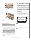
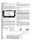
Air Shutter Adjustment
The Medina gas insert has an air shutter control lever located
behind the lower door on the insert's face and to the left of
the gas valve (see Figures 14 & 15). The lever is linked to
the primary air shutter on the main burner. The air shutter
regulates the amount of primary air the burner receives and
therefore how clean the insert burns. The air shutter should
only be adjusted by a qualified gas technician. The insert
should burn for about 15 minutes with the logs installed
before adjusting the air shutter. More air will result in shorter
flames and less color, less air will result in bigger flames
and more color. To adjust the air shutter, insert a regular
screwdriver into the slide adjustment and slide it side to side
(see Figures 14 & 15).
Caution: The air shutter should never
be set so as to make the tips of the flames sooty or create
sooting on the viewing glass, logs, or heat exchanger. If
soot begins to form after burning, the air shutter should
be opened gradually until the sooting condition stops.
Gas quality and gas pressure may vary, which can affect
the burning characteristics of the insert.
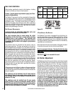
Fuel
Type
Inlet Pressure Manifold Pressure
Desired Minimum Maximum On Hi
Fire
On Lo
Fire
Natural
Gas
7" WC 5" WC 10.5" WC 3.5" WC 1.7" WC
LP Gas 11" WC 10.5" WC 13" WC 10" WC 5.4” WC
Robertshaw Millivolt Gas Valve
TP/TH
TH
TP
Inlet (Supply)
Pressure Tap
Figure 13
The Manifold
(Outlet) Tap