


Page 35
XC17 SERIES
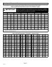
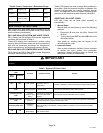
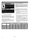
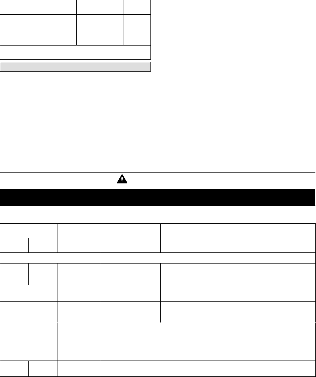
Table 8. Sensor Temperature / Resistance Range
Sensor
Temperature
Range °F (°C)
Resistance values
range (ohms)
Pins/Wire
Color
Outdoor
(Ambient)
−40ºF to 140ºF
(−40ºC to 60ºC)
280,000 to 3750 3 and 4
(Black)
Discharge −35ºF to 310ºF
(−37ºC to 154ºC)
41,000 to 103 1 and 2
(Yellow)
Note: Sensor resistance decreases as sensed temperature increases
(see Figures 6 and 7).
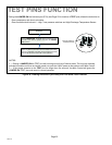
Main Control LED Alert Codes
Main Control LED alert codes (simply referred to as LED
alert codes) are located on the Main Control and marked
with the following identification.
DS11 AND DS14 LED SYSTEM AND ALERT CODES
DS11 (Green) and DS14 (Red) LEDs indicate diagnostics
conditions that are listed in Table 9.
These LEDs display fault conditions in system cooling
capacity, dehumidification mode, anti−short cycle lockout,
high and low pressures, discharge line temperature,
outdoor temperature, and discharge sensor failures.
DS15 AND DS13 LED COMPRESSOR ALERT CODES
DS15 (Yellow) and DS13 (Red) LEDs indicate diagnostics
conditions that are listed in Table 9.
These LEDs display the most common fault conditions in
the system. When an abnormal condition is detected, this
function communicates the specific condition through
LEDs. The diagnostic function is capable of detecting both
mechanical and electrical system abnormal conditions.
RESETTING LED ALERT CODES
LED alert codes can be reset either manually or
automatically:
1. Manual Reset
Manual reset can be achieve by one of the following
methods:
S Disconnect R wire from the Main Control’s R
terminal.
S Turning main power OFF and then ON at the unit’s
disconnect switch.
After power up, existing code will display for 60
seconds and then clear.
2. Automatic Reset
After an alert is detected, the Main Control continues
to monitor the unit’s system and compressor
operations. When/if conditions return to normal, the
alert code is turned off automatically.
IMPORTANT
LED alert codes do not provide safety protection. The is a monitoring function only and cannot control or shut down other
devices.
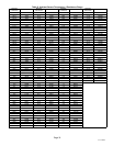
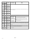
Table 9. System LED Alert Codes
Outdoor Main Control
LEDs
Condition Possible Cause(s) Solution
DS11
Green
DS14 Red
SYSTEM STATUS
OFF OFF Power problem
No power (24V) to control
terminals R and C or
control failure.
1
Check control transformer power (24V).
2
If power is available to control and LED(s) do not light, replace control.
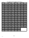
Simultaneous SLOW
Flash
Normal operation
Unit operating normally or
in standby mode.
Indicates that control has internal component failure. Cycle 24 volt pow-
er to control. If code does not clear, replace control.
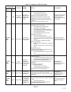
Alternating SLOW
Flash
5−minute
anti−short cycle
delay
Initial power up, safety trip,
end of room thermostat
demand.
None required (Jumper FIELD TEST pins to override)
Simultaneous FAST
Flash
Ambient Sensor
Problem
Sensor being detected open or shorted or out of temperature range. control will revert to time/temper-
ature defrost operation. (System will still heat or cool).
Alternating FAST Flash
Coil Sensor
Problem
This model does not utilize a coil sensor, however this alert indicates either an open or shorted circuit.
See if 10K resistor is not damage or missing. Resistor is located in the sensor harness assembly,
brown lead.
ON ON
Main Control
Board Failure
Indicates that control has internal component failure. Cycle 24 volt power to control. If code does not
clear, replace control.