


Page 14
506510−01
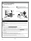
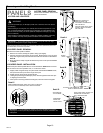
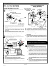
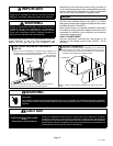
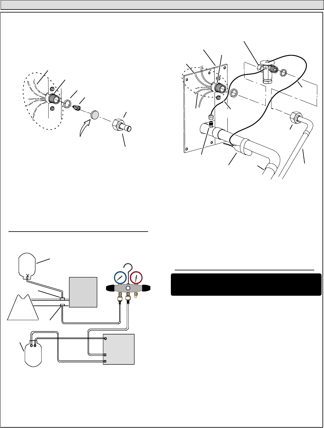
Flushing the System
SENSING
LINE
TEFLON RING
FIXED ORIFICE
(Uncased Coil Shown)
BRASS NUT
LIQUID LINE ASSEMBLY
(INCLUDES STRAINER)
LIQUID LINE ORIFICE HOUSING
DISTRIBUTOR TUBES
DISTRIBUTOR
ASSEMBLY
REMOVE AND DISCARD
WHITE TEFLON SEAL (IF
PRESENT)
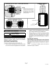
A On fully cased coils, remove the coil access and plumbing panels.
B Remove any shipping clamps holding the liquid line and distributor
assembly.
C Using two wrenches, disconnect liquid line from liquid line orifice
housing. Take care not to twist or damage distributor tubes during
this process.
D Remove and discard fixed orifice, valve stem assembly if present
and Teflon washer as illustrated above.
E Use a field−provided fitting to temporary reconnect the liquid line to
the indoor unit’s liquid line orifice housing.
TYPICAL FIXED ORIFICE REMOVAL PROCEDURE
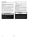
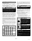
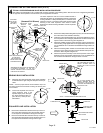
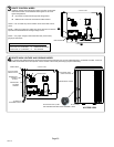
TYPICAL CHECK EXPANSION VALVE
REMOVAL PROCEDURE
TWO PIECE PATCH PLATE
(UNCASED COIL ONLY)
VAPOR
LINE
DISTRIBUTOR
ASSEMBLY
DISTRIBUTOR
TUBES
LIQUID
LINE
MALE EQUALIZER
LINE FITTING
EQUALIZER
LINE
CHECK
EXPANSION
VALVE
TEFLON
RING
(Uncased Coil Shown)
STUB END
TEFLON
RING
SENSING BULB
LIQUID LINE
ORIFICE
HOUSING
LIQUID LINE
ASSEMBLY WITH
BRASS NUT
A On fully cased coils, remove the coil access and plumbing panels.
B Remove any shipping clamps holding the liquid line and distributor as-
sembly.
C Disconnect the equalizer line from the check expansion valve equaliz-
er line fitting on the vapor line.
D Remove the vapor line sensing bulb.
E Disconnect the liquid line from the check expansion valve at the liquid
line assembly.
F Disconnect the check expansion valve from the liquid line orifice hous-
ing. Take care not to twist or damage distributor tubes during this pro-
cess.
G Remove and discard check expansion valve and the two Teflon rings.
H Use a field−provided fitting to temporary reconnect the liquid line to the
indoor unit’s liquid line orifice housing.
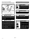
LOW
HIGH
EXISTING
INDOOR unit
GAUGE
MANIFOLD
INVERTED HCFC−22
CYLINDER CONTAINS
CLEAN HCFC−22 TO BE
USED FOR FLUSHING.
LIQUID LINE SERVICE
VALVE
INLET
DISCHARGE
TANK
RETURN
CLOSED
OPENED
RECOVERY
CYLINDER
RECOVERY MACHINE
NEW
OUTDOOR
UNIT
VAPOR LINE
SERVICE VALVE
VAPOR
LIQUID
1
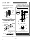
A Inverted HCFC−22 cylinder with clean refrigerant to the vapor service
valve.
B HCFC−22 gauge set (low side) to the liquid line valve.
C HCFC−22 gauge set center port to inlet on the recovery machine with
an empty recovery tank to the gauge set.
D Connect recovery tank to recovery machines per machine
instructions.
CONNECT GAUGES AND EQUIPMENT FOR
FLUSHING PROCEDURE
A
B
C
D
B
OR
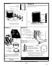
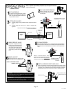
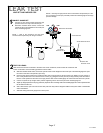
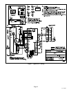
FLUSHING LINE SET
A Set the recovery machine for liquid recovery and start the recov-
ery machine. Open the gauge set valves to allow the recovery
machine to pull a vacuum on the existing system line set and in-
door unit coil.
B Invert the cylinder of clean HCFC−22 and open its valve to allow
liquid refrigerant to flow into the system through the vapor line
valve. Allow the refrigerant to pass from the cylinder and through
the line set and the indoor unit coil before it enters the recovery
machine.
C After all of the liquid refrigerant has been recovered, switch the
recovery machine to vapor recovery so that all of the HCFC−22
vapor is recovered. Allow the recovery machine to pull down to 0
the system.
D Close the valve on the inverted HCFC−22 drum and the gauge
set valves. Pump the remaining refrigerant out of the recovery
machine and turn the machine off.
The line set and indoor unit coil must be flushed with at least the
same amount of clean refrigerant that previously charged the sys-
tem. Check the charge in the flushing cylinder before proceeding.
LINE SET AND INDOOR COIL (1 OF 2)
FLUSHING
1
2
3
CAUTION Ċ This procedure should not be performed on sys-
tems which contain contaminants (Example compressor burn
out.