


Note - It is recommended that rack be converted
to 20 inch filter size if filter is installed elsewhere
in return air duct.
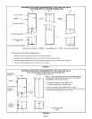
3-In applications where rack uses a 16 inch
(50.8cm) filter, remove filler piece before cutting
rack opening. See figure 4.
4 - Cut four strips from rollofadhesive-backedfoam
tape (provided) to fit filter rack flanges, Apply to
flanges.
5 - Secure filter rack to cabinet as shown in figure 4.
6 - Cut opening in filter rack as shown in figure 4,
7 - In applications where rack uses a 16 inch (50,8cm)
filter, remove rack from cabinet, re-install filler
piece, then re-install rack to cabinet.
8-Install existing filter, unless filter is located
elsewhere in the return air duct,
9- Attach door to filter rack with thumb screws
provided.
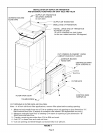
II - Internal Filter Rack
(Used with kit CAT#16L25)
Note - If filter is not to be located inside of unit,
installation of this filter kit is not required.
1 - Lay G26 unit on its side and cut out return air
opening in cabinet at knockout guides, See G26
installation instructions.
2 - Install filter rack top and bottom inside unit as
shown in figure 5, tn right side installations
wiring must be carefully worked around.
3 - Install existing filter,
4 - Slide door into filter rack bottom seam and align
with filter rack top securing hole. Attach with
thumb screws provided.
5- Securewiring awayfrom filter access areawith two
provided wire ties. Use existing screws in existing
screw locations to prevent accidental damage to
control board(s)/wiring by drilling of new holes.
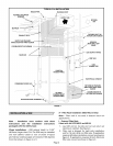
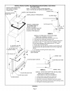
B - Supply Air Transition Installation
1 - Cut four strips from roll ofadhesive-backedfoam
tape (provided) to fit supply air transition flanges
at G26 unit connection. Apply to flanges. See
figure 4 or 5,
2- Position supply air transition on unit top as
shown in figure 4 or 5.
3- If required, internally insulate transition with
foil-faced insulation (field provided) and fasten
with kit provided insulation pins and washers,
4- Use four screws and/or bend cabinet flanges
over transition tips to secure transition.
C - Unit Installation
1 - Align unit with existing supply air plenum (coil
cabinet in air conditioning applications) and
return air plenum.
Note - If required, use existing G14 isomode pads
to achieve this alignment.
2 - Make connections to unit, In bottom return air
applications, follow the instructions provided
with the G26 unit, note especiallythe warnings in
the "Return Air Opening Guidelines" section.
3 - ff air conditioning coil was removed, re-install
coil, reconnect line set and coil drain. See
condensing unit installation instructions for
re-processing of refrigerant system.
Note - Coil drain line must not be connected to
heat exchanger condensate drain line. If lines
were connected, debris from evaporator could
affect heat exchanger operation.
4- Make tow voltage wiring entrance to unit on
opposite side from return air connection to
prevent blocking filter access. Connect as
illustrated in G26 installation instructions.
5 - Connect high voltage wiring as outlined in G26
installation instructions,
6- Connect gas piping as outlined in G26
installation instructions.
Consult local codes for flexible connector
installation restrictions on G26 furnace.
7 - Connect venting as outlined in G26 installation
instructions.
Note - Mufflers can not be used in G26
installation. Check existing venting for size
(diameter and length). It should meet the
specifications as outlined in G26 installation
instructions.
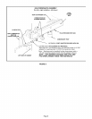
8 - Connect heat exchanger condensate drain line as
shown in figure 6 and as outlined in G26 unit
installation instructions, (A 1/2" PVCto 1/2" CPVC
bushing is provided for connecting PVC to
existing CPVC condensate line,)
9 - Continue with Unit Start-up Section as outlined
in G26 installation instructions.
Note - See G26 installation instructions for heat
anticipation settings.
Page 4