


_ Techrlloal
GAS UNITS j _:_bic=lo.s
KITS AND ACCESSORIES LithoU,S.A,
©1997 Lennox industries inc.
Datlas, Texas
503,770M
10/97
FURNACE TRANSITION KIT
INSTALLATION INSTRUCTIONS FOR FURNACE TRANSITION KIT CAT# 16L23
(LB-89657A), CAT# 16L24 (LB-89657B), AND CAT# 16L25 (LB-89658A),USED WHEN
CONVERTING FROM G14 UNITS TO G26 UNITS (UPFLOW)
Package 1 of 1 contains:
1 - Supply airtransition
1 - External Filter rack (used with kit CAT# 16L23 and
16L24)
1 - Internal filter rack top piece (used with kit CAT#
16L25)
1 - Internal filter rack bottom piece (used with kit
CAT# 16L25)
1 - Filter rack door
1 - Roll of adhesive-backed foam tape (1/8" thick x
5/16" wide)
8- Insulation pins
8- Insulation washers
1 - 1/2" CPVC x 1/2"PVC bushing
2 - Wire ties (used with kit CAT# 16L25)
Check all components for shipping damage. Consult
last carrier immediately if damage is found.
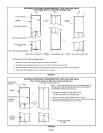
Table 1 shows furnace transition kit usage. These kits
are used when replacing an existing G14 upflow
furnace with a G26 upflow furnace. It allows
installation of the G26 furnace without modification
of the existing supply and side return air plenums.
Bottom return air applications do not require the
provided filter rack,
G14 installations with air conditionh_g - G 14removal
may require raising of coil, or partially or fully
removing the coil. If coil needs to be removed, line
sets may need to be cut, which in turn requires system
pump-down or refrigerant recovery depending on
type of service valves provided on condensing unit or
ambient outdoor temperatures.
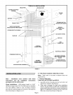
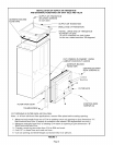
Refer to figure 1 for typical G14 installation.
A - G14 units without air conditioning
1 - Set the thermostat to the lowest setting,
2 - Disconnect electrical power to G14 unit,
3- Shut off gas to G14 unit.
4 - Disconnect supply air plenum at unit top.
5 - Remove control access panel,
6 - Cut combustion air intake pipe and exhaust pipe
in location(s) which will allow convenient
reconnection of pipes to G26 unit, and/or
removal of muffler(s) (if installed). Remove
muffler(s) (if installed), Support intake and
exhaust pipes to prevent damage to pipe joints,
7 - Cut condensate drain line in a location which will
allow convenient reconnection with G26 unit.
8 - Disconnect gas line at unit.
9 - Disconnect power wiring at unit.
10 -Disconnect low voltage wiring at unit.
11 -Remove blower access panel.
TABLE 1
G14 CABINET WIDTH G26 CABINET WIDTH KIT CAT# (LB#)
inches (mm) inches (mm)
Q3-40 21-1/4 (540) Q2/Q3-50 16-1/4 (413) 16L23 (LB-89657A)
Q3-60 21-1/4 (540) Q3-50 or Q3-75 16-1/4 (413) 16L23 (LB-89657A)
Q4-60 21-1/4 (540) Q4/5-75 21-1/4 (540) 16L25 (LB-89658A)
Q3-80 21-1/4 (540) Q3-75 16-1/4 (413) 16L23 (LB-89657A)
Q4-80 21-1/4 (540) Q4/5-75 21-1/4 (540) 16L25 (LB-89658A
Q5-80 26-1/4 (667) Q4/5-75 21-1/4 (540) 16L24 (LB-89657B)
Q3-100 26-1/4 (667) Q3/4-100 21-1/4 (540) 16L24 (LB-89657B)
Q4/5-t00 26-1/4 (667) Q4/5-100 21-1/4 (540) 16L24 (LB-89657B)
Page 1