


Page 51
19 − Thoroughly rinse and drain the heat exchanger. Soap
solutions can be corrosive. Take care to rinse entire
assembly.
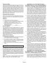
20 − Reinstall heat exchanger into cabinet making sure that
the clamshells of the heat exchanger assembly are
resting on the support located at the rear of the cabi-
net. Remove the indoor blower to view this area
through the blower opening.
21 − Re-secure the supporting screws along the vestibule
sides and top to the cabinet.
22 − Reinstall cabinet screws on front flange at blower
deck.
23 − Reinstall the primary limit on the vestibule panel.
24 − Route heating component wiring through hole in blow-
er deck and reinsert strain relief bushing.
25 − Reinstall electrical junction box.
26 − Reinstall the cold end header box.
27 − Reinstall the combustion air inducer. Reconnect the
combustion air inducer to the wire harness.
28 − Reinstall pressure switches and reconnect pressure
switch wiring.
29 − Carefully connect combustion air pressure switch
hosing from pressure switches to proper stubs on
cold end header collector box.
30 − Reinstall condensate trap.
31 − Reinstall burner box assembly in vestibule area.
32 − Reconnect exhaust piping and exhaust drain tubing.
33 − Reconnect flame roll−out switch wires.
34 − Reconnect sensor wire and reconnect 2−pin plug from
ignitor.
35 − Secure burner box assembly to vestibule panel using
four existing screws. Make sure burners line up in
center of burner ports.
36 − Reinstall gas valve manifold assembly. Reconnect
gas supply line to gas valve.
37 − Reinstall burner box cover.
38 − Reconnect 2−pin plug to gas valve.
39 − Replace the blower compartment access panel.
40 − Refer to instruction on verifying gas and electrical con-
nections when re−establishing supplies.
41 − Follow lighting instructions to light and operate fur-
nace for 5 minutes to ensure that heat exchanger is
clean and dry and that furnace is operating properly.
42 − Replace heating compartment access panel.
Cleaning the Burner Assembly
1 − Turn off electrical and gas power supplies to furnace.
Remove upper and lower furnace access panels.
2 − Disconnect the 2−pin plug from the gas valve.
3 − Remove the burner box cover.
4 − Disconnect the gas supply line from the gas valve. Re-
move gas valve/manifold assembly.
5 − Mark and disconnect sensor wire from the sensor. Dis-
connect 2-pin plug from the ignitor at the burner box.
6 − Remove four screws which secure burner box assem-
bly to vest panel. Remove burner box from the unit.
7 − Use the soft brush attachment on a vacuum cleaner to
gently clean the face of the burners. Visually inspect
the inside of the burners and crossovers for any block-
age caused by foreign matter. Remove any blockage.
8 − Reconnect the sensor wire and reconnect the 2−pin
plug to the ignitor wiring harness.
9 − Reinstall the burner box assembly using the existing
four screws. Make sure that the burners line up in the
center of the burner ports.
10 − Reinstall the gas valve manifold assembly. Reconnect
the gas supply line to the gas valve. Reinstall the burn-
er box cover.
11 − Reconnect 2−pin plug to gas valve.
12 − Replace the blower compartment access panel.
13 − Refer to instruction on verifying gas and electrical con-
nections when re−establishing supplies.
14 − Follow lighting instructions to light and operate fur-
nace for 5 minutes to ensure that heat exchanger is
clean and dry and that furnace is operating properly.
15 − Replace heating compartment access panel.