


Page 47
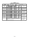
Proper Combustion
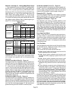
Furnace should operate minimum 15 minutes with correct
manifold pressure and gas flow rate before checking com-
bustion. Take combustion sample beyond the flue outlet
and compare to the tables below. The maximum carbon
monoxide reading should not exceed 50 ppm.
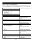
TABLE 28
High Fire
SLP98DFV Unit CO
2
%
For
Nat
CO
2
%
For
L.P.
070V36B
7.6 − 8.6 9,1 − 10.1
090V36C
090V60C
110V60C
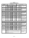
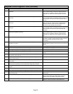
TABLE 29
Low Fire
Unit CO
2
%
For
Nat
CO
2
%
For
L.P.
070V36B
5.3 − 6.3 6.8 − 7.8
090V36C
090V60C
110V60C
Manifold Pressure Measurement
To correctly measure manifold pressure, the differential
pressure between the positive gas manifold and the nega-
tive burner box must be considered. Use pressure test
adapter kit (available as Lennox part 10L34) to assist in
measurement.
1 − Remove the threaded plug from the outlet side of the
gas valve and install a field−provided barbed fitting.
Connect test gauge +" connection to barbed fitting to
measure manifold pressure.
2 − Tee into the gas valve regulator vent hose and connect
test gauge −" connection.
3 − Start unit on low heat (35% rate) and allow 5 minutes
for unit to reach steady state.
4 − While waiting for the unit to stabilize, notice the flame.
Flame should be stable and should not lift from burner.
Natural gas should burn blue.
5 − After allowing unit to stabilize for 5 minutes, record
manifold pressure and compare to value given in table
27.
6 − Repeat steps 3, 4 and 5 on high heat.
NOTE − Shut unit off and remove manometer as soon as an
accurate reading has been obtained. Take care to remove
barbed fitting and replace threaded plug.
CAUTION
Do not attempt to make adjustments to the gas valve.
Other Unit Adjustments
Primary Limit
The primary limit is located on the heating compartment
vestibule panel. This limit is factory set and require no ad-
justment.
Flame Rollout Switches (Two)
These manually reset switches are located on the burner
box.
Pressure Switches (Two)
The pressure switches are located in the heating compart-
ment on the combustion air inducer. These switches check
for proper combustion air inducer operation before allow-
ing ignition trial. The switches are factory−set and require
no adjustment. Pressure switch tubing installation is critical
for safe operation. See figure 46.
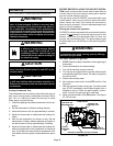
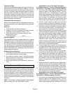
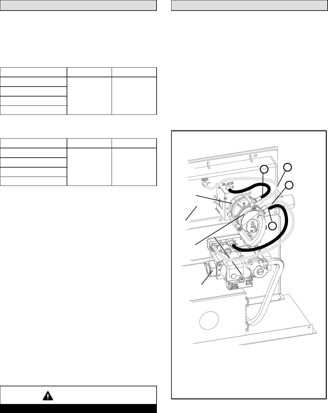
PRESSURE SWITCH TUBING INSTALLATION
FIGURE 46
1
2
3
4
Gas Valve
Cold End
Header Box
High−Fire
Pressure
Switch
Low−Fire
Pressure
Switch
1 − Black hose from front port on low−fire pressure switch to
positive port on the gas valve.
2 − Red hose from rear port on low−fire pressure switch to the
negative port on the gas valve.
3 − Red hose from front port on high−fire pressure switch to
negative port on cold end header box.
4 − Black hose from rear port on high−fire pressure switch to
positive port on cold end header box.