


Page 39
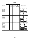
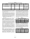
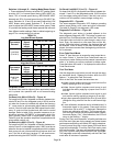
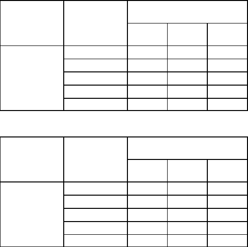
Switches 14 through 19 −− Heating Mode Blower Speed
−− These switches are factory set at the OFF position which
provides 100 % of normal speed during HIGH HEAT de-
mand, 70% of normal speed during MID−RANGE HEAT
demand and 35% of normal speed during LOW HEAT de-
mand. Switches 14, 15 and 16 are used to adjust the LOW
HEAT blower motor speed. Switches 17, 18 and 19 are
used to adjust the HIGH HEAT blower motor speed. Table
21 provides the heating mode blower speeds that will result
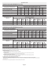
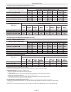
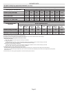
from different switch settings. Refer to tables beginning on
page 37 for corresponding cfm values.
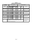
TABLE 21
Low Heat Blower Speeds
Thermostat
Demand
Blower
Speed
Adjust-
ments
DIP SWITCH SETTINGS
14 15 16
Low Heat
(R to W1)
+15% On Off On
+7.5% On Off Off
Normal Off Off Off
−7.5% On On Off
−15% On On On
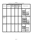
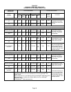
TABLE 22
High Heat Blower Speeds
Thermostat
Demand
Blower
Speed
Adjust-
ments
DIP SWITCH SETTINGS
17 18 19
High Heat
(R to
W1 & W2)
+15% On Off On
+7.5% On Off Off
Normal
Off Off Off
−7.5% On On Off
−15% On On On
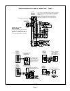
On−Board Links
On−Board links must be clipped (when applicable) before
unit is placed into operation with a non−communicating
thermostat.
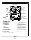
On−Board Link W914 (DS to R) −− Figure 44
On−board link W914 is a clippable connection between ter-
minals DS and R on the integrated control. W914 must be
cut when the furnace is installed with either the Harmony
IIIt zone control or a thermostat which features humidity
control. If the link is left intact the PMW signal from the Har-
mony III control will be blocked and also lead to control
damage. Refer to table 24 for operation sequence in ap-
plications including SLP98DFV, a thermostat which fea-
tures humidity control and a single−speed outdoor unit.
Table 25 gives the operation sequence in applications with
a two−speed outdoor unit.
On−Board Link W951 (R to O) −− Figure 44
On−board link W951 is a clippable connection between ter-
minals R and O on the integrated control. W951 must be cut
when the furnace is installed in applications which include a
heat pump unit and a thermostat which features dual fuel
use. If the link is left intact, terminal O" will remain ener-
gized eliminating the HEAT MODE in the heat pump.
On−Board Link W915 (Y1 to Y2) −− Figure 44
On−board link W915 is a clippable connection between ter-
minals Y1 and Y2 on the integrated control. W915 must be
cut if two−stage cooling will be used. If the link is not cut the
outdoor unit will operate in second−stage cooling only.
Diagnostic LED −− Figure 44
The seven−segment diagnostic LED displays operating
status, target airflow, error codes and other information.
The table on Page 53 lists diagnostic LED codes.
Diagnostic Push Button −− Figure 44
The diagnostic push button is located adjacent to the
seven−segment diagnostic LED. This button is used to en-
able the Error Code Recall mode and the Field Test mode.
Press the button and hold it to cycle through a menu of op-
tions. Every five seconds a new menu item will be dis-
played. When the button is released, the displayed item will
be selected. Once all items in the menu have been dis-
played, the menu resumes from the beginning until the but-
ton is released.
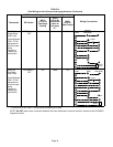
Error Code Recall Mode
Select "E" from the menu to access the most recent ten er-
ror codes. Select c" from the Error Code Recall menu to
clear all error codes. Button must be pressed a second time
while c" is flashing to confirm command to delete codes.
Press the button until a solid ≡" is displayed to exit the Error
Code Recall mode.
Field Test Mode
Use the diagnostic push button to scroll through the menu
as described above. Release the button when the LED
flashes −" to select the Field Test mode.
While in the Field Test mode the technician can:
D Initiate furnace ignition and move to and hold low−fire
rate by applying a R to W1 jumper.
D Initiate furnace ignition sequence and move to and
hold high−fire rate by applying a jumper from R to W1
and W2.
D Initiate furnace ignition sequence and move to and
hold mid−fire rate by applying a jumper to R and W2.
D Apply then remove the jumper from R to W1 and W2 to
change the firing rate from low fire to mid fire and high
fire.
D A vent calibration sequence can be initiated even if a
thermostat signal is not present. Press and hold the
push button until a solid C" is displayed. Release the
button and calibration will begin. The furnace will per-
form the high−fire and low−fire pressure switch calibra-
tions and display CAL". After calibration, the LED will
return to the flashing −" display.
During Field Test mode operation, all safety switches are
still in the circuit (they are not by−passed) and indoor blower
performance and timings will match DIP switch selections.
Current furnace firing rate, indoor blower CFM and flame
signal will be displayed. To exit the Field Test mode, press
and hold the button. The menu will resume from the begin-
ning. Also, cycle the main power to exit the Field Test mode.
The integrated control will automatically exit the Field Test
mode after 45 minutes of operation.