


Page 20
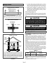
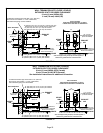
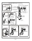
FIGURE 22
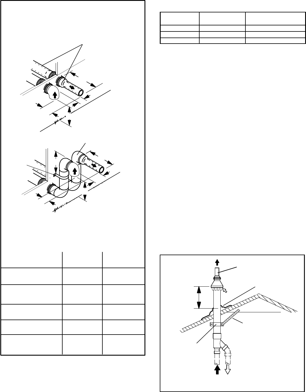
FIELD−SUPPLIED WALL TERMINATION OR
(15F74) WALL RING TERMINATION KIT
With INTAKE ELBOW
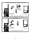
See venting table 7 for maximum venting lengths with this
arrangement.
* Use wall support every 24" (610 mm). Use two wall supports if
extension is greater than 24" (610 mm) but less than 48" (1219
mm). NOTE − One wall support must be 6" (152 mm) from top of
each pipe (intake and exhaust).
2" (51mm)
Vent Pipe
3" (76mm)
Vent Pipe
12" (508MM) 12" (508MM)
6" (152MM) 6" (152MM)
6" (152MM)
12" (305MM) 20" (508MM)
6" (152MM) 6" (152MM)
6" (152MM)
A−Minimum clearance
above grade or average
snow accumulation
B−Maximum horizontal
separation between
intake and exhaust
C−Minimum from
end of exhaust to
inlet of intake
D−Maximum exhaust
pipe length
E−Maximum wall support
distance from top of each
pipe (intake/exhaust)
NOTE − FIELD−PROVIDED
REDUCER MAY BE
REQUIRED TO ADAPT
LARGER VENT PIPE SIZE
TO TERMINATION.
D
B
C
SIZE TERMINATION
PER TABLE 9
1/2" (13mm) ARMAFLEX
INSULATION IN UN-
CONDITIONED SPACE
STRAIGHT
APPPLICATION
B
C
D
* WALL
SUPPORT
1/2" (13mm) ARMAFLEX INSULATION
IN UNCONDITIONED SPACE
E
EXTENDED
APPLICATION
A
A
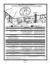
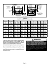
TABLE 9
EXHAUST PIPE TERMINATION SIZE REDUCTION
SLP98DFV
MODEL
Exhaust Pipe Size Termination Pipe Size
*070 2", 2−1/2" or 3" 1−1/2"
*090 2", 2−1/2" or 3" 2"
110 2", 2−1/2" or 3" 2"
*SLP98DF −070 and −090 units with the flush−mount ter-
mination must use the 1−1/2" accelerator supplied with the
kit.
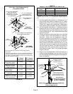
5 − On field−supplied terminations for side wall exit, ex-
haust piping may extend a maximum of 12 inches
(305mm) for 2" PVC and 20 inches (508mm) for 3"
(76mm) PVC beyond the outside wall. Intake piping
should be as short as possible. See figures 20 and 22.
6 − On field−supplied terminations, a minimum distance
between the end of the exhaust pipe and the end of
the intake pipe without a termination elbow is 8" and a
minimum distance of 6" with a termination elbow. See
figures 20 and 22.
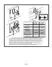
7 − If intake and exhaust piping must be run up a side wall
to position above snow accumulation or other ob-
structions, piping must be supported every 24"
(610mm) as shown in figures 20 and 22. In addition,
close−coupled wall termination kits must be extended
for use in this application. See figures 30 and 31.
When exhaust and intake piping must be run up an
outside wall, the exhaust piping must be terminated
with pipe sized per table 9.The intake piping may be
equipped with a 90° turndown elbow. Using a turn-
down elbow will add 5 feet (1.5m) to the equivalent
length of the pipe.
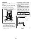
8 − Based on the recommendation of the manufacturer, a
multiple−furnace installation may use a group of up to
four terminations assembled together horizontally, as
shown in figure 25.
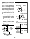
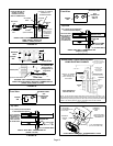
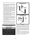
FIGURE 23
DIRECT VENT CONCENTRIC ROOFTOP TERMINATION
71M80, 69M29 or 60L46 (US)
41W92 or 41W93 (Canada)
Minimum
Above Average
Snow
Accumulation
SHEET METAL STRAP
(Clamp and sheet metal strap
must be field installed to support
the weight of the termination kit.)
FLASHING
(Not Furnished)
CLAMP
FIELD−PROVIDED
REDUCER MAY BE REQUIRED
TO ADAPT LARGER VENT
PIPE SIZE TO TERMINATION
INTAKE
1−1/2" (38mm) accelerator
provided on 71M80 &
44W92 kits for
SLP98DFV−36B−070
12” (305mm)