


Step 16. Turn on gas supply and test for gas leaks using a gas leak test
solution (see Test Procedure on Page 16 of the Installation and
Operation Manual).
Step 18. Reinstall the log set and glass door assembly. See Page 10
(Log Set Installation) and Page 22 (Door Assembly Installation)
in the Installation and Operation Manual.
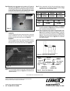
Step 19. Light the appliance per the lighting instructions label on ap-
pliance (located below glass door) or lighting instructions on
Page 17 of the Installation and Operation Manual. Inspect for
proper pilot and burner flame appearances (see Figures 15 and
16 below). Also see Flame Color and Behavior and Inspect The
Pilot System For Proper Flame on Page 18 of the Installation
and Operation Manual.
Figure 16 - Burner Flame Appearance
No Blue Flame
Center
Soot at
Flame Tip
Dark Orange
Flame
IMPROPERLY
BURNING FLAME
Soot above
Flame Tip
No Soot at
Flame Tip
PROPERLY
BURNING FLAME
Semi-Transparent
Yellow Flame
Blue Flame
Center
Ports on Pan
Burner Assembly
Figure 15 - Proper Pilot Flame Appearance
Safety Label
Figure 14
Inlet Gas Supply Pressure
Fuel # Minimum Maximum Desired
Nat.
Gas
5" WC/po. C.E
(1.24 kPa)
10.5" WC/po. C.E
(2.61 kPa)
7" WC/po. C.E
(1.74 kPa)
Manifold Gas Supply Pressure
Fuel # Low High
Natural
Gas
(Lo) 1.8" WC/po. C.E
(0.45 kPa)
(Hi) 3.5" WC/po. C.E
(0.87 kPa)
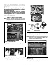
Step 14. Re-Install burner, and make sure air shutter is 1/8” open for
Natural Gas (see Figure 13). The proper air shutter adjustment
may need to be adjusted from standard depending upon variables
in the installation. After step 19, with the appliance lit and fully
warmed up, evaluate the burner flame appearance and re-adjust
air shutter for proper flame appearance, if necessary.
Figure 13
Check Air Shutter
for Proper Gap
Through This Hole
Burner
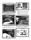
Step 15.
35,000 BTU
If you are using the #34 orifice remove the sticker on the label
to show “VISION 35” on the Label. The label is located on the
inside the lower flip down control door (see Figure 14).
25,000 BTU
If you are using the #42 orifice, adhere the VISION 25 sticker
over the VISION 35 on the safety label. The label is located on
the inside the lower flip down control door (see Figure 14).
Step 17. Using a manometer, test the inlet and manifold gas pressure
per instructions in the Installation and Operation Manual (Page
16) and as shown in the following 2 tables.
Sticker
4
Printed in U.S.A. © 2007 Lennox Hearth Products
P/N 775,236M REV. B 03/2008
Lennox reserves the right to make changes at any time, without notice, in design,
materials, specifications, prices and also to discontinue colors, styles and products.
Consult your local distributor for fireplace code information.
1110 West Taft Avenue • Orange, CA 92865
NOTE: DIAGRAMS AND ILLUSTRATIONS ARE NOT TO SCALE.