


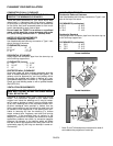
INSTALLATION
PAGE 7
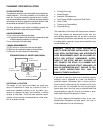
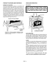
BAFFLE PLATES
This appliance has two heavy steel baffle plates that are
installed in the upper firebox (over the steel secondary
air supply tubes). During shipment and installation, the
baffle plates might slide around, and may need to be
repositioned (lined up to each other) and pushed to the
back wall in order for the stove to operate properly.
When in the proper position, the rear edges of the baffle
plates should be flush to the back wall of the firebox.
See Removing Baffle Plates for Cleaning on page 17 for
additional information on installing baffle plates.
INSTALLING LEG LEVELERS
The four leg levelers (included in accessory package),
screw into the tapped (threaded) holes on the bottom of
the four legs. Level the stove by adjusting the screws in
or out.
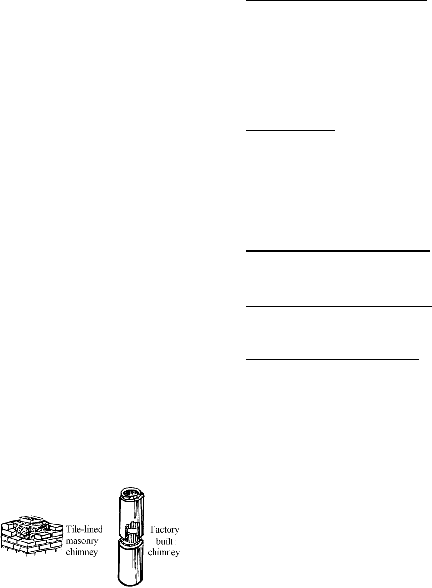
TYPES OF CHIMNEYS
The chimney is a vital part of your stove installation. A
properly built masonry chimney or a properly installed
factory built chimney will assure a consistent draft under
a variety of weather conditions (a smoking stove is usu-
ally caused by a chimney problem). The stove flue size
is 6 inches diameter, which is approximately 28 square
inches minimum. The maximum flue size should be no
more than (3)-three times the cross sectional area of
the size of the stove flue collar. In this case, that would
be no larger than a 10-inch diameter stack, or approxi-
mately 85 square inches maximum.
All chimneys must be installed as specified by local
building codes and according to the chimney manufac-
turer instructions (in the case of a factory built chimney).
See the chimney manufacturer instructions for exact
specifications. Factory built chimneys must comply with
UL 103HT or ULC S629.
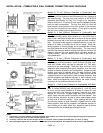
ACCEPTABLE CONNECTOR PIPE FOR INSTALLA-
TIONS
For Standard Residential Clearances: Six (6) inch
minimum, single wall, 25 gage minimum thickness,
stove pipe is acceptable. Three (3) pre-drilled holes are
provided in the flue collar for fastening the pipe securely
to the stove. Use sheet metal screws to do this. Addi-
tional sections of single wall pipe should be fastened
together with at least three (3) sheet metal screws each
section. When connecting to the factory built ceiling
support package, use the manufacturer's transition
piece, usually called a dripless connector, to join single
wall pipe to their factory built chimney section.
Minimum Flue Size: The required minimum diameter
and area required for the flue size is (respectively) 6
inches / 152 mm diameter, which is approximately 28
square inches / 711 square mm. The maximum flue size
should be no more than (3) three times the cross sec-
tional area of the size of the 6 inches / 152 mm diameter
flue collar. In this case, that would be no larger than a
10 inch (254 mm) diameter (area = approx. 85 sq.
inches [216 sq. cm]).
Connection To A Factory Built Chimney: This space
heater is to be connected to a factory-built chimney
conforming to CAN / ULC – S629, Standard for 650°C
Factory-Built Chimneys.
For Reduced Residential Clearances: Type L and
listed double wall connector pipe is acceptable. Install
any factory built brand of pipe according to the manu-
facturer's instructions.
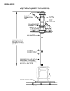
Vapor Barrier At Chimney Penetration
Install all venting components per the Vent Manufactur-
ers installation instructions. Ensure that there is an ef-
fective vapor barrier at the location where the chimney
penetrates to the exterior of the structure. This can be
accomplished by applying a non-hardening waterproof
sealant to the following components:
• Around the chimney at the point where the storm
collar will meet the chimney just above the Flashing.
• Along the vertical seam of the chimney pipe, where
it is exposed to the weather.
• On each nail head on the flashing.
• Around the chimney at the point where the storm
collar will meet the chimney just above the flashing.
Notes:
• On a flat or tarred and graveled roofs, nail and seal
the flat roof flashing to the roof on all sides with
roofing compound.
• Do not put screws through the flashing into the
chimney pipe.