


3
NOTE: DIAGRAMS & ILLUSTRATIONS NOT TO SCALE.
Figure 3
MAINTENANCE
As part of an annual inspection, the termination should be checked for
any foreign debris, animal or insect nests, or material of any kind which
may have become lodged in it. The exterior of the termination should be
visually inspected for damage of any kind.
In the event of damage to the termination, it should be replaced with a
new termination. All screw attachments should be checked to insure
they have not loosened over time and they should also be checked for
the water tightness of their silicon seal. The termination must be
removed to clean the chimney. Following cleaning, reinstall the termi-
nation and inspect as detailed in this document.
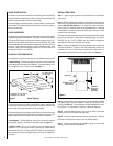
Figure 4
VERTICAL VENT TERMINATION CLEARANCES
These instructions should be used as a guideline and do not super-
sede local codes in any way. Install SV4.5 vent according to the current
National Fuel Gas Code, ANSI-Z223.1 - latest edition, in the USA or CAN/
CGA-B149.1 and B149.2 - latest editions in Canada.
Terminate single vent caps relative to building components according to
Figure 4
.
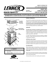
2"
(Max.)
Chase
Flashing
3"
(Max.)
Pipe
Section
Chase
2 feet
(Max.)
1 foot
(Min.)
Strap
Support
2"
(Min.)
12
X
Roof Pitch is X/12
2 FT
MIN.
2 FT MIN.
Lowest
Discharge
Opening
H*
Horizontal Overhang
Vertical
Wall
Vent
Termination
*H = MINIMUM HEIGHT FROM ROOF TO
LOWEST DISCHARGE OPENING OF VENT
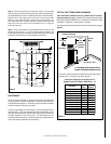
The vent/air intake termination clearances above the high side of
an angled roof is as shown in the following chart:
Termination Heights For Vents Above Flat Or
Slopped Roofs Ref. NFPA 54 / ANSI Z223.1, 7.6
hctiPfooR
H
)teef(
H
)sretem(
21/6ottalF0.13.0
21/7ot21/6revO52.183.0
21/8ot21/7revO5.164.0
21/9ot21/8revO0.216.0
21/01ot21/9revO5.267.0
21/11ot21/01revO52.399.0
21/21ot21/11revO0.422.1
21/41ot21/21revO0.525.1
21/61ot21/41revO0.638.1
21/81ot21/61revO0.731.2
21/02ot21/81revO5.792.2
21/12ot21/02revO0.844.2
Step 8. Once the termination is positioned, secure it to the chase
flashing using the stainless steel screws provided, through the pre-
punched attachment holes in the attachment tabs of the termination.
Be careful not to over tighten the screws so as to strip out the chase
flashing. In the event of a strip, a larger screw can be used so long
as it is stainless steel. DO NOT use common sheet metal screws, as
they will corrode over time and the termination will no longer be
secure at that point.
Step 9. Once the termination is permanently attached, seal all of the
screw tops with silicone. In order to properly apply the silicone, the
surface of the termination and screws must be clean and dry. Not sealing
the screws tops will result in water leakage into the chase.