


39
NOTE: DIAGRAMS & ILLUSTRATIONS ARE NOT TO SCALE.
LENNOX HEARTH PRODUCTS • MERIT
®
PLUS DIRECT VENT GAS FIREPLACES (MPD33/35/40/45) • INSTALLATION INSTRUCTIONS
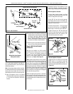
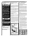
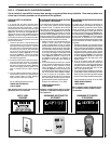
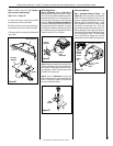
Burner Assembly
Gas Valve
Assembly
Orifice
Figure 67
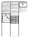
Millivolt Appliances
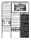
Step 4. SIT Systems - Refer to Figure 68 and
the instructions provided with the kit. Using a
Torx T20, remove and discard the three pressure
regulator mounting screws. Remove the pres-
sure regulator, spring, poppet, diaphragm and
bushing. Discard all removed components.
Ensure the rubber gasket installed on the back of
the replacement pressure regulator is properly
positioned and install the new pressure regula-
tor using the new screws supplied with the kit.
Tighten screws to 25 In. lb. torque.
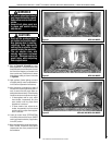
Pressure
Regulator
Remove
These
Components
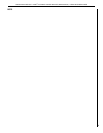
Pilot
Orifice
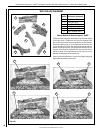
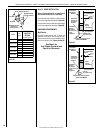
Figure 70
Spring
Adjusting
Screw
Slotted
Cap
PSI
OFF
I
ON
CONTROL
IGNITE
Manifold
Pressure
Test Port
Inlet Pressure Test Port
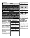
Electronic Appliances
Step 7. Honeywell Electronic Valves - See
Figure 70 and the instructions provided with
the kit. Remove the slotted cap screw, o-ring,
pressure-regulating adjusting screw and spring.
Retain all parts for possible later use. Install
new components from the kit. Black cap and
red spring for propane gas units. Silver cap
and stainless steel spring for natural gas units.
Before installing the cap, attach manometer to
the manifold side pressure test fitting and adjust
screw until pressure reads 3.5 inches water
column (0.87 kPa) for natural gas, and 10.0
inches water column (2.49 kPa) for propane gas.
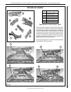
Step 5. Attach manometer to the manifold side
pressure test fitting and verify manifold pres-
sure reads 3.5 inches water column (0.87 kPa)
for natural gas, and 10.0 inches water column
(2.49 kPa) for propane gas.
Step 6. Refer to Figure 69 and remove the
pilot hood assembly to access the hexed pilot
orifice. Remove and replace the orifice with
the one provided with the kit.
Figure 68
Step 2. Carefully remove the logs. Exercise
care so as not to break the logs.
Step 3. Refer to Figure 67.
A. Above the burner, remove the two baffle
securing screws. Remove the baffle.
B. Remove the two screws securing the trap-
ezoidal plate to the burner. Remove the plate.
C. Remove the burner assembly with attached
venturi tube.
Figure 69