


14
NOTE: DIAGRAMS & ILLUSTRATIONS ARE NOT TO SCALE.
LENNOX HEARTH PRODUCTS • MERIT
®
PLUS DIRECT VENT GAS FIREPLACES (MPD33/35/40/45) • INSTALLATION INSTRUCTIONS
Note: Convert inches into metric equivalent
measurement, as follows:
Millimeters (mm) = Inches x 25.4
Centimeters (cm) = Inches x 2.54
Meters (M) = Inches x .0254
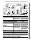
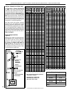
TRAHCHTGNELNOITCESTNEV
lanimoN
htgneLnoitceS
)sehcni(
6 21 42 63 84
T
O
T
A
L
Q
T
Y
noitceSteN
)sehcni(htgneL
2/1-4 2/1-01 2/1-22 2/1-43 2/1-64
tneVfothgieH snoitceStneVforebmuN
sehcni tf
5.4 573.0 1 0 0 0 0 1
9 57.0 2 0 0 0 0 2
5.01 578.0 0 1 0 0 0 1
51 52.1 1 1 0 0 0 2
5.91 526.1 2 1 0 0
0
3
12 57.1 0 2 0 0 0 2
5.22 578.1 0 0 1 0 0 1
5.52 521.2 1 2 0 0 0 3
5.13 526.2 0 3 0 0 0 3
5.43 578.2 0 0 0 1 0 1
5.73 521.3 1 1 1 0 0 3
5.34 526.3 0 2 1 0 0 3
54 57.3 0 0 2 0 0 2
5.64 578.3 0 0 0 0 1 1
5.94 521.4 1 0 2 0 0 3
15 52.4 1 0 0 0 1 2
5.55 526.4 0 1 2 0 0 3
75 57.4 0 0 1 1 0 2
66 52.5 0 2 2 0 0 4
5.76 526.5 0 0 3 0 0 3
96 57.5 0 0 0 2 0 2
27 6 1 0 3 0 0 4
5.37 521.6 1 0 0 2 0 3
5.97 526.6 0 1 0 2 0 3
18 57.6 0 0 0 1 1 2
09 5.7 0 2 1 0 1 4
5.
19
526.7 0 0 2 0 1 3
39 57.7 0 0 0 0 2 2
69 8 1 0 1 2 0 4
5.79 521.8 1 0 0 0 2 3
201 5.8 2 0 0 0 2 4
5.301 526.8 0 0 0 3 0 3
801 9 1 0 0 3 0 4
411 5.9 0 2 0 0 2 4
711 57.9 1 0 5 0 0 6
5.811 578.9 1 1 0 3 0 5
621 5.01 0 0 1 3 0 4
5.031 578.01 1 0 1 3 0 5
531 52.11 0 0 6 0 0 6
831 5.11 0 0 0 4 0 4
5.931 526.11 0 0 0 0 3 3
5.241 578.11 1 0 0 4 0 5
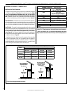
TRAHCHTGNELNOITCESTNEV
noitceSlanimoN
)sehcni(htgneL
6 21 42 63 84
T
O
T
A
L
Q
T
Y
noitceSteN
)sehcni(htgneL
2/1-4 2/1-01 2/1-22 2/1-43 2/1-64
tneVfothgieH snoitceStneVforebmuN
sehcni tf
441 21 1 0 0 0 3 4
051 5.21 0 1 0 0 3 4
5.451 578.21 1 1 0 0 3 5
5.061 573.31 0 2 0 0 3 5
5.271 573.41 0 0 0 5 0 5
771 57.41 1 0 0 5 0 6
381 52.51 0 1 0 5 0 6
681 5.51 0 0 0 0 4 4
5.091 578.51 1 0 0 0 4 5
5.691 573.61 0 1 0 0 4 5
5.502 521.71 0 1 1 5 0 7
702 52.71 0 0 0 6 0 6
5.112 526.71 1 0 0 6 0 7
5.712 521.81 0 1 0 6 0 7
5.922 521.91 0 0 1 6 0 7
5.232 573.91 0 0 0 0 5 5
732 57.91 1 0 0 0 5 6
5.142 521.02 0 0 0 7 0 7
642 5.02 1 0 0 7 0 8
252 12 0 1 0 7 0 8
462 22 0 0 1 7 0 8
672 32 0 0 0 8 0 8
972 52.32 0 0 0 0 6 6
5.
082 573.32
1 0 0 8 0 9
5.382 526.32 1 0 0 0 6 7
5.982 521.42 0 1 0 0 6 7
5.103 521.52 0 0 1 0 6 7
5.013 578.52 0 0 0 9 0 9
513 5.62 1 0 0 9 0 01
5.523 521.72 0 0 0 0 7 7
033 5.72 1 0 0 0 7 8
633 82 0 1 0 0 7 8
543 57.82 0 0 0 01 0 01
5.943 521.92 1 0 0 01 0 11
273 13 0 0 0 0 8 8
5.673 573.13 1 0 0 0 8 9
5.973 526.13 0 0 0 11 0 11
5.814 578.43 0 0 0 0 9 9
324 52.53 1 0 0 0 9 01
564 57.83 0 0 0 0 01 01
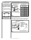
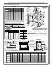
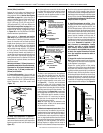
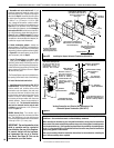
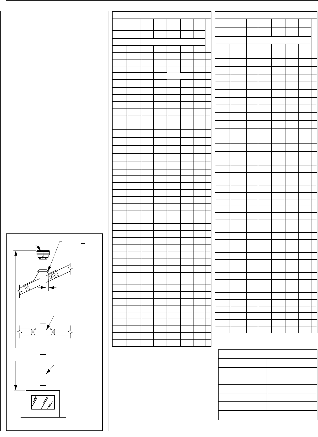
SV4.5FA or
SV4.5FB Flashing
AND SV4.5SC
Storm Collar
SV4.5VF
Firestop/Spacer*
1 in (25.4 mm)
Minimum
Clearance to
Combustibles
SV4.5CGV-1
Termination
SV4.5L6/12/24/36/48
Vent Sections
*When using Secure Flex,
use Firestop/Spacer
SF4.5VF.
Max. 40 ft
(12.2 m)
Effective Vent Length
Model Effective Length
SV4.5L6 4-1/2"
SV4.5L12 10-1/2"
SV4.5L24 22-1/2"
SV4.5L36 34-1/2"
SV4.5L48 46-1/2"
Table 7
Figure 20
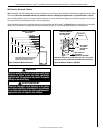
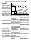
VERTICAL TERMINATION SYSTEMS (ROOF)
See Figure 20 and Figures 30 through 32
on Page 17 and their associated Vertical
Vent Tables, which illustrate the various verti-
cal venting configurations that are possible for
use with these appliances. Secure Vent™ pipe
applications are shown in these Figures; Secure
Flex™ pipe may also be used. A Vertical Vent
Table summarizes each system’s minimum and
maximum vertical and horizontal length values
that can be used to design and install the vent
components in a variety of applications.
Both these vertical vent systems terminate
through the roof. The minimum vent height
above the roof and/or adjacent walls is speci-
fied in ANSI Z223.1-(latest edition) (In Canada,
the current CAN/CSA-B149.1 installation code)
by major building codes. Always consult your
local codes for specific requirements. A general
guide to follow is the Gas Vent Rule (refer to
Figure 5 on Page 6).
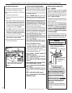
Vertical (Straight) Installation
(Figure 20)
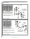
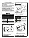
Determine the number of straight vent sec-
tions required. 4-1/2" (114 mm), 10-1/2" (267
mm), 22-1/2" (572 mm), 34-1/2" (876 mm)
and 46-1/2" (1181 mm) net section lengths
are available (see Tables on this page and
Pages 35 and 36 - Vent Sections). Plan the
vent lengths so that a joint does not occur at
the intersection of ceiling or roof joists. Refer
to the Vent Section Length Chart.