


18
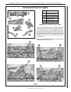
NOTE: DIAGRAMS & ILLUSTRATIONS ARE NOT TO SCALE.
LENNOX HEARTH PRODUCTS • MERIT
®
PLUS DIRECT VENT GAS FIREPLACES (MPD33/35/40/45) • CARE AND OPERATION INSTRUCTIONS
LENNOX HEARTH PRODUCTS
1508 Elm Hill Pike, Suite 108
Nashville, TN 37210
visit us at www.Lennox.com
1-800-9-LENNOX
PRODUCT REFERENCE INFORMATION
We recommend that you record the important
reference information about your fireplace in
the space provided below.
Please call Lennox Hearth Products for the
phone number of your nearest Lennox Hearth
Products dealer who will answer your questions
or address your concerns.
When ordering repair parts, always give the
following information:
1. The model number of the appliance.
2. The serial number of the appliance.
3. The part number.
4. The description of the part.
5. The quantity required.
6. The installation date of the appliance.
If you encounter any problems or have any
questions concerning the installation or ap-
plication of this system, please contact your
dealer or distributor.
ORDERING REPLACEMENT PARTS
A complete parts list is found at the end of
this manual. Use only parts supplied from the
manufacturer.
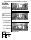
With proper care and maintenance, your appli-
ance will provide many years of enjoyment. If
you should experience any problem, first refer
to the troubleshooting guide in this manual. If
problem persists, contact your Lennox Hearth
Products dealer or distributor.
Normally, all parts should be ordered through
your Lennox Hearth Products distributor or dealer.
Parts will be shipped at prevailing prices at
time of order.
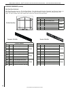
1. If any of the original wire as supplied must be replaced,
1. it must be replaced with Type AWM 105°C – 18 GA. wire.
2. 120V, 60Hz – Less than 3 amps.
BK
Transf.
120 V.
24 V
Factory Wired Field Wired
BL
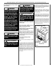
Electronic Wiring Diagram (Honeywell)
Showing the Blower Wiring for the Optional
FBK-250 Kits
R
WH
BL
W
Gas Valve
B
R
IGNITER
BK
Schematic Representation Only
*ON/OFF Switch (Integral
with Gas Valve)
Optional
FBK-250
Module
*Leave the ON/OFF switch, which is integral
with the gas valve, in the ON position.
G
OPTIONAL APPLIANCE-MOUNTED ON/OFF SWITCH
OR OPTIONAL WALL SWITCH OR OPTIONAL THERMOSTAT
OR OPTIONAL REMOTE RECEIVER
PILOT
ASSEMBLY
OPT
BLOWER
Junction Box
White
Green
Red
Black
Neutral
Side of
Receptacle
Tab Intact
Green
Ground
Screw
Hot
Side of
Receptacle
Tab
Broken
Optional
Accessory
Switch
120 VAC - Black
neerG-dnuorG
etihW-lar
t
ueN
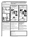
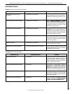
1. If any of the original wire as supplied must be replaced,
1. it must be replaced with Type AWM 105°C – 18 GA. wire.
2. 120V, 60Hz – Less than 3 amps.
BK
Transf.
120 V.
24 V
Factory Wired Field Wired
BL
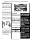
Electronic Wiring Diagram (Honeywell)
Showing the Blower Wiring for the Optional
FBK-100 and FBK-200 Kits
R
W
BL
W
Gas Valve
B
R
IGNITER
BK
*Blower speed control switch is provided in FBK200 blower kit.
Schematic Representation Only
**ON/OFF Switch (Integral
with Gas Valve)
**Leave the ON/OFF switch, which is integral
with the gas valve, in the ON position.
OPTIONAL APPLIANCE-MOUNTED ON/OFF SWITCH
OR OPTIONAL WALL SWITCH
OR OPTIONAL THERMOSTAT
OR OPTIONAL REMOTE RECEIVER
G
OPT
BLOWER
PILOT
ASSEMBLY
Junction Box
White
Green
Red
Black
Neutral
Side of
Receptacle
Tab Intact
Green
Ground
Screw
Hot
Side of
Receptacle
Tab
Broken
120 VAC - Black
neerG-dnuorG
Optional
Accessory
Switch
etihW-lar
t
ueN
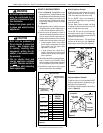
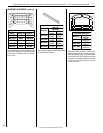
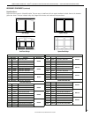
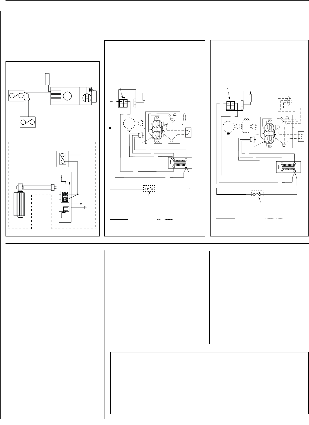
WIRING DIAGRAMS
Wiring diagrams are provided here for reference
purposes only. This information is also provided
on schematics attached directly to the appliance
on a pullout panel located within the control
compartment.
CAUTION: LABEL ALL WIRES PRIOR TO DISCONNECTION WHEN SERVICING
CONTROLS. WIRING ERRORS CAN CAUSE IMPROPER AND DANGEROUS
APPLIANCE OPERATION.
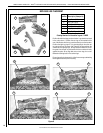
TP-TH
TP
TH
APPLIANCE- MOUNTED
ON/OFF SWITCH
(OPTIONAL)
BK/W(1)
BK/W(1)
WALL-MOUNTED ON/OFF SWITCH (OPTIONAL)
THERMOSTAT (OPTIONAL)
JUNCTION BOX
BLACK
W
GR
120 V
AC
WALL MOUNTED CONFIGURATION FOR FAN SWITCH (OPTIONAL)
BK
R
WIRING DIAGRAM MILLIVOLT GAS VALVES
THERMOPILE
GAS VALVE
FAN
(OPTIONAL)
Fireplace Model Number ________________________________________________
Fireplace Serial Number _________________________________________________
Date Installed _________________________________________________________
Type of Gas Used in Fireplace ____________________________________________
Dealer Name _________________________________________________________