


17
NOTE: DIAGRAMS & ILLUSTRATIONS ARE NOT TO SCALE.
LENNOX HEARTH PRODUCTS • MERIT
®
PLUS DIRECT VENT GAS FIREPLACES (MPD33/35/40/45) • CARE AND OPERATION INSTRUCTIONS
WARNING
• Air shutter adjustment should
only be performed by a
qualified professional ser-
vice technician.
• Ensure front glass panel is
in place and sealed during
adjustment.
CAUTION
• Soot will be produced if
the air shutter is closed too
much. Any damage due
to sooting, resulting from
improperly setting the air
shutter, is not covered under
the warranty.
• The air shutter door and
nearby appliance surfaces
are HOT. Exercise caution to
avoid injury while adjusting
flame appearance.
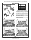
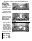
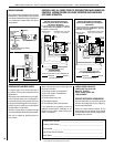
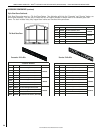
BURNER FLAME ADJUSTMENTS
1. Refer to Figures 10, 11, and 12 for proper
flame appearance. To adjust the flame, rotate
the adjustment rod toward the back or toward
the front of the fireplace (rod located in the
lower control area). Position the air shutter
to the factory setting as shown in the table
in Figure 13.
2. Light appliance (follow lighting procedure
on lighting label in control compartment or
in this Care and Operation Instructions).
3. Allow the burner to operate for at least 15
minutes while observing the flame continu-
ously to ensure that the proper flame ap-
pearance has been achieved. If the following
conditions are present, adjust accordingly.
• If flame appears weak or sooty, adjust
the air shutter, incrementally, to a more
open position until the proper flame
appearance is achieved.
• If flame remains blue, adjust the air
shutter, incrementally, to a more closed
position until the proper flame appear-
ance is achieved.
4. When satisfied that the burner flame appear-
ance is normal, turn the ON/OFF control
(unit-mounted or remote switch, depending
on your application) to the OFF position.
5. Reinstall the lower control access panel,
then proceed to finish the installation.
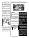
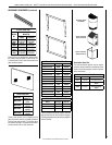
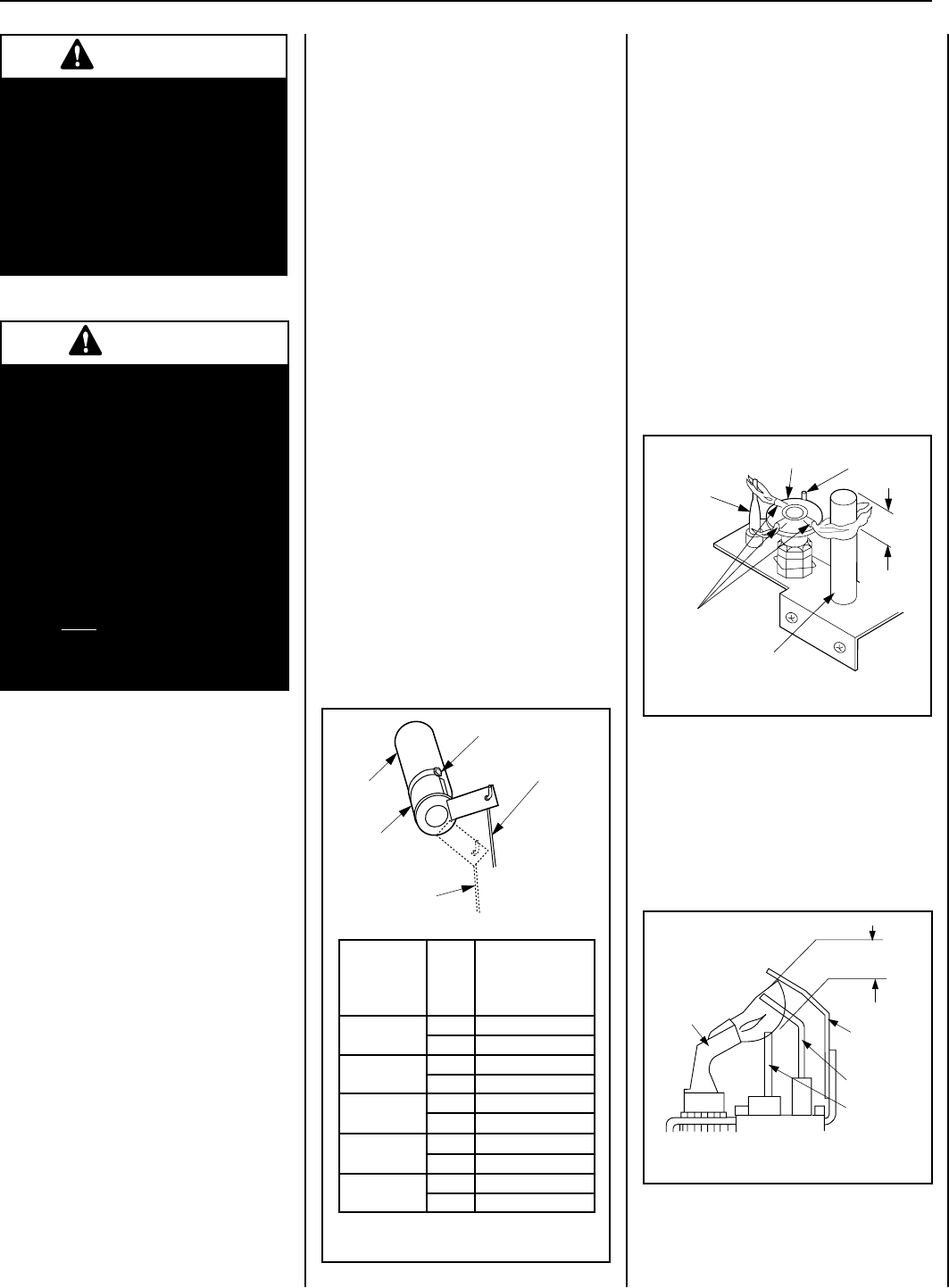
Millivolt Appliance Checkout
To light the burner, rotate the gas valve control
knob counterclockwise to the ON position
(“ON” will be at the top side of the valve).
Turn the ON/OFF control (unit-mounted or
remote switch, depending on your application)
to the ON position.
The pilot flame should be steady, not lifting
or floating. Flame should be blue in color with
traces of orange at the outer edge.
The top 3/8" (10 mm) at the pilot generator
(thermopile) and the top 1/8" minimum (tip)
of the quick drop out thermocouple should be
engulfed in the pilot flame.
The flame should project 1" (25 mm) beyond
the hood at all three ports (see Figure 14).
Replace logs if removed for pilot inspection.
Electronic Appliance Checkout
To light the burner, turn the integrated ON/OFF
switch (or optional switch, depending on your
application) to the ON position.
The pilot flame should engulf the flame rod, as
shown in Figure 15.
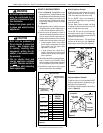
MILLIVOLT
Thermocouple
Hood Igniter Rod
3/8" Min
(9 mm)
Thermopile
Pilot
Nozzels
Figure 14
ELECTRONIC
Proper Flame
Adjustment
Pilot
Nozzle
3/8 To 1/2 Inch
(9 mm to 13 mm)
Ground
Electrode
Flame Rod
Hot Surface
Igniter
Figure 15
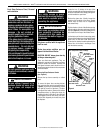
Figure 13
Adjustment Rod Up
(Fully Open Position)
Air Shutter
Burner Tube
Adjusting Set Screw
Adjustment Rod Down
(minimum air
opening position)
sledoM
saG
epyT
RIAYROTCAF
RETTUHS
GNITTES
)mm(sehcni
8233-TDPM
.taN 23/1 )8.O(
.porP 61/3 )67.4(
8233-RDPM
.taN 23/1 )8.O(
.porP 61/3 )67.4(
0353-DPM
.taN 23/1 )8.O(
.porP 61/3 )67.4(
5304-DPM
.taN 8/1 )2.3(
.porP 2/1 )31(
0454-DPM
.taN 8/1 )2.3(
.porP 2/1 )31(