


13
NOTE: DIAGRAMS & ILLUSTRATIONS ARE NOT TO SCALE.
LENNOX HEARTH PRODUCTS • MERIT
®
PLUS DIRECT VENT GAS FIREPLACES (MPD33/35/40/45) • INSTALLATION INSTRUCTIONS
Use only approved vent components (see
Approved Vent Components on Page 2).
These fireplaces must be vented directly
to the outside.
The vent system may not service multiple
appliances, and must never be connected to a
flue serving a solid fuel burning appliance. The
vent pipe is tested to be run inside an enclosed
wall (such as a chase). There is no requirement
for inspection openings in the enclosing wall at
any of the joints in the vent pipe.
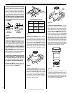
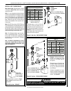
Installation of Vent Restrictor
A vent restrictor may be needed with this ap-
pliance, install vent restrictor (provided) in the
appliance top flue outlet as shown in Figure 18
(MPDT-3328, MPD-3530, MPD-4035 and MPD-
4540) or rear flue outlet as shown in Figure 19
(MPD-3530, MPD-4035 and MPD-4540). It is
held in place by friction, only.
Note: The vent restrictor is included in the
firebox.
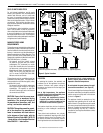
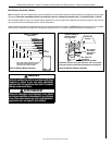
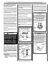
Step 3. PREPARING APPLIANCE VENT
COLLAR (MPD-3530/4035/4540 models
with combined top/rear vent)
Each of the unit’s two vent collars are sealed
with a cover plate and a seal plate and gasket.
The cover, and seal plate and gasket must be
removed from the vent collar being used. Refer
to Figure 16 for top vent usage and Figure 17
for rear, and the following steps to prepare the
appropriate collar for use.
From the vent collar being used, remove the four
screws securing the vent seal plate and gasket.
Remove and discard the seal plate and gasket.
When the top vent collar is being used, from
inside the firebox, loosen the two screws in the
keyhole slots of the cover plate and remove the
remaining two cover plate securing screws.
Remove and discard the cover plate. Reinstall
and securely tighten all four screws.
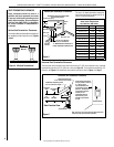
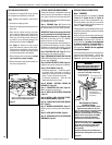
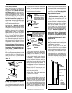
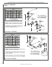
When the rear vent collar is being used, from
inside the firebox, remove the two screws se-
curing the lintel to the rear wall of the firebox,
then remove the lintel. Remove the four cover
plate securing screws. Remove and discard
the cover plate.
Reinstall and securely tighten all four cover
plate screws. Re-secure the lintel to the rear
wall of the firebox.
Figure 18
VENT SEAL PLATE
GASKET
FIREBOX TOP
CABINET TOP
SECURING
SCREWS
VENT
COVER PLATE
TOP VENT
ON MPD-3530/4035/4540 SERIES MODELS
(COMBINED TOP AND REAR VENT UNITS)
TOP VENT SEAL & COVER PLATE REMOVAL
WHEN USING THE TOP VENT
COVER PLATE
SECURING SCREWS
CROSS SECTION
(INSIDE UNIT)
(OUTSIDE UNIT)
VENT SEAL PLATE
GASKET
SECURING
SCREWS
CROSS SECTION
LINTEL
SECURING
SCREWS
LINTEL
REAR VENT
COVER PLATE
SECURING SCREWS
ON MPD-3530/4035/4540 SERIES MODELS
(COMBINED TOP AND REAR VENT UNITS)
REAR VENT SEAL & COVER PLATE REMOVAL
WHEN USING THE REAR VENT
CABINET BACK
(INSIDE UNIT)
(OUTSIDE UNIT)
Figure 17
Figure 16
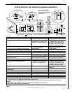
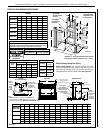
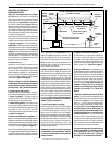
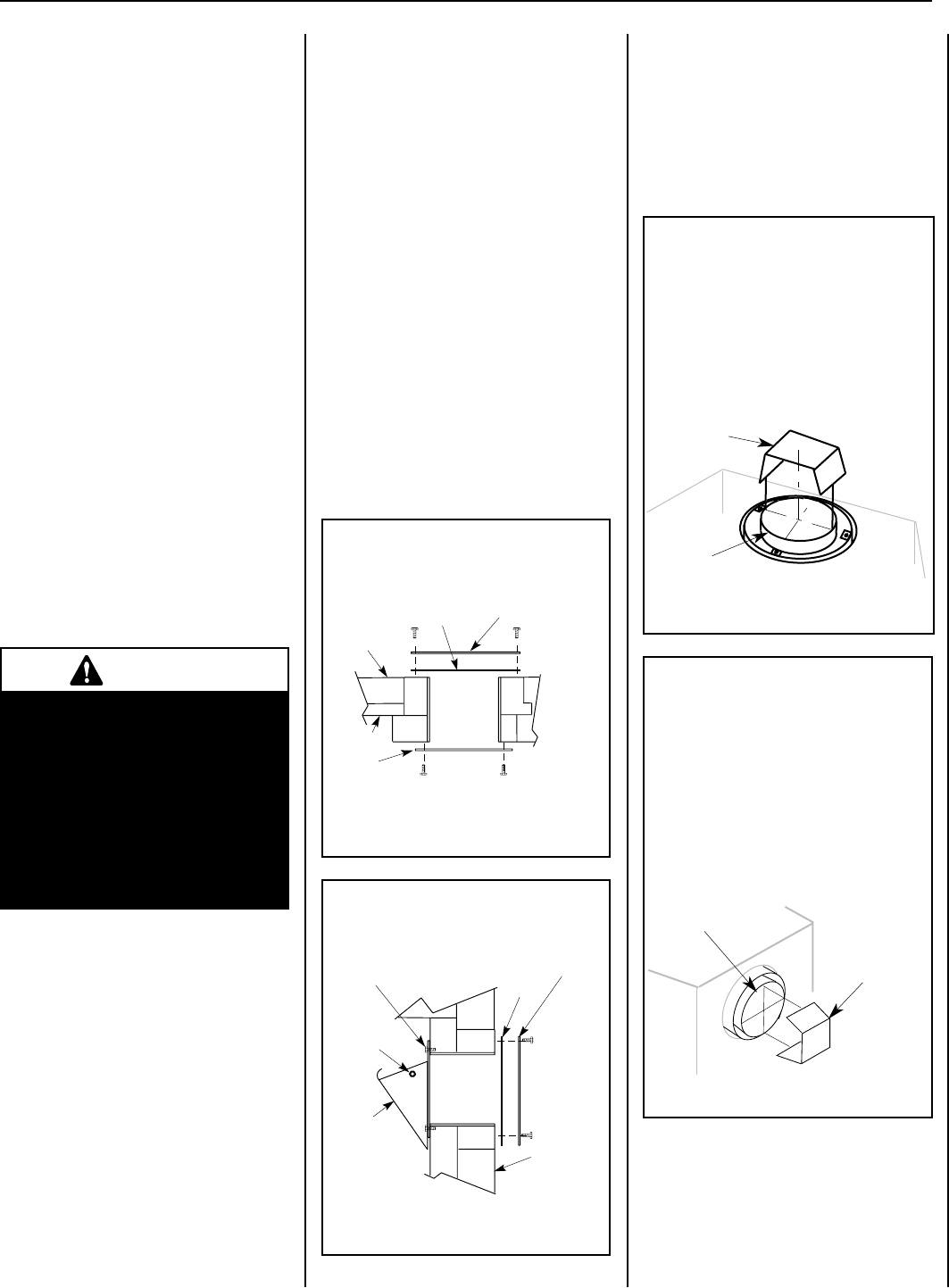
A vent restrictor may be needed when
vertically terminating the vent system above
the roof (when using the appliance top vent),
install vent restrictor in the top vent of the
fireplace outlet on MPD-3530/4035/4540
and MPDT-3328 series models.
RESTRICTOR
APPLIANCE TOP
VENT OUTLET
VENT RESTRICTOR INSTALLATION
(TOP VENT)
If needed, install the restrictor orientated as
shown, either from inside or outside the unit,
in the inner fireplace collar.
INNER
FIREPLACE
COLLAR
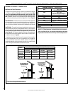
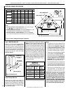
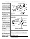
RESTRICTOR
APPLIANCE REAR
VENT OUTLET
A vent restrictor may be needed when
horzontally terminating the vent system from
the rear of the appliance (when using the
appliance rear vent), install vent restrictor in
the rear vent of the fireplace outlet on
MPD-3530/4035/4540 series models, in any
installation that has a vertical vent run in
excess of three feet (0.914 meters).
VENT RESTRICTOR INSTALLATION
(REAR VENT)
INNER FIREPLACE
COLLAR
If needed, install the restrictor orientated as
shown, either from inside or outside the unit,
in the inner fireplace collar.
Figure 19
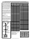
Step 4. INSTALLING VENT SYSTEM
These instructions should be used as a
guideline and do not supersede local codes
in any way. Install venting according to local
codes, these instructions, the current National
Fuel Gas Code (ANSI-Z223.1) in the USA or
the current standards of CAN/CSA-B149.1
in Canada.
Ensure clearances are in accordance with
local installation codes and the requirements
of the gas supplier.
Dégagement conforme aux codes d'installa-
tion locaux et aux exigences du foumis-
seunde gaz.
Select Venting System - Horizontal or Vertical
With the appliance secured in framing, determine
vent routing and identify the exterior termina-
tion location. The following sections describe
vertical (roof) and horizontal (exterior wall)
vent applications. Refer to the section relating
to your installation. A list of approved venting
components are shown on Pages 34 and 35.
WARNING
Failure to reinstall and securely
tighten cover plate screws could
result in leakage of flue products
into the living space. Vent cover
plate and vent seal cap must
remain securely in stalled on
unused vent collar. Failure to
do so could result in leakage of
flue products into living space.