


26
NOTE: DIAGRAMS & ILLUSTRATIONS ARE NOT TO SCALE.
LENNOX HEARTH PRODUCTS • MERIT
®
PLUS DIRECT VENT GAS FIREPLACES (MPD33/35/40/45) • INSTALLATION INSTRUCTIONS
Note: Remote receiver should be located in the
wall, or if installed in the control compartment,
pulled all the way forward and completely to the
left or right against the corner posts.
6. If wall-mounted ON/OFF control or thermo-
stat is to be used, mount it in a convenient
location on a wall near the fireplace.
7. If an optional control is to be used, wire it in
the low voltage circuit as shown in Figures
48 and 49.
Note: The supplied 15 feet of 2 conductor wire
has one end of each conductor connected to
the gas valve circuit and the other end of each
conductor placed loose inside the bottom
compartment.
8. If the optional control switch is installed,
turn the appliance-mounted ON/OFF burner
control switch to the OFF position.
9. After the wiring is complete, replace the
cover plate.
Note: The gas valve-mounted ON/OFF switch
is shown in Figures 48 and 49. It is integral
with the gas valve and should be set to the
ON position.
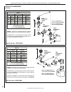
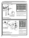
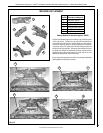
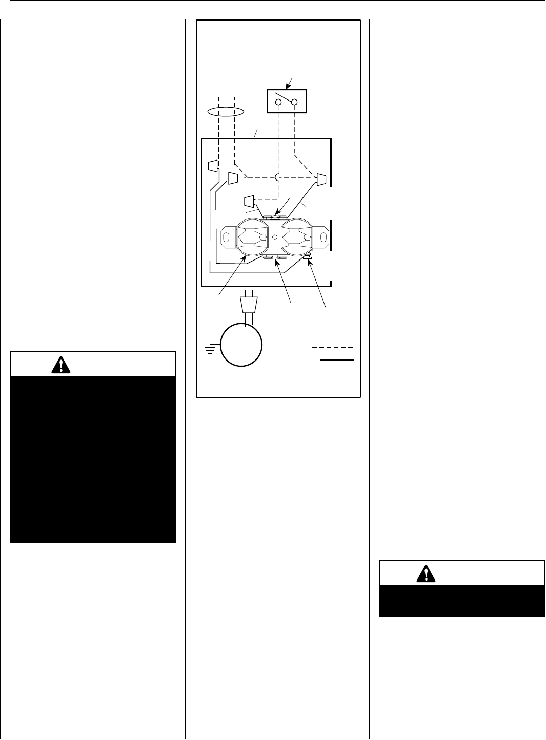
BLOWER CONTROL CIRCUIT WIRING
120V, 60HZ, 1PH
Factory Wired
Ground
Field Wired
Junction Box
Tab Intact
Tab
Broken
Plug blower
into this
receptacle
neerG - dnuorG
* Wall-mounted
ON/ OFF Blower
Switch or Variable
Speed Control Switch.
Blower
etihW - lar
t
ueN
120 VAC - Black
Green
Ground
Screw
White
Green
Neutral
Side of
Receptacle
Hot
Side of
Receptacle
Red
Black
Figure 50: Junction Box Wiring
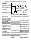
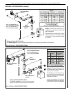
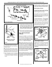
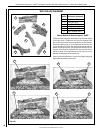
A sediment trap is recommended in the gas
piping within the home to prevent moisture
and debris in the line from damaging the valve.
These appliances are equipped with a gas flex
line for use (where permitted) in connecting the
unit to the gas line. A gas flex line is provided
to aid in attaching the direct vent appliance to
the gas supply. The gas flex line can only be
used where local codes permit. Refer to Figure
51 for flex line description. The flex line is rated
for both natural and propane gas. A manual
shut off valve is also provided with the flex line.
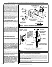
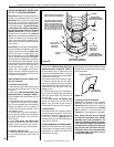
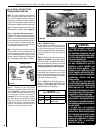
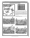
The gas control valve is located in the lower
control compartment.
To access the valve open the lower control
compartment door (see Figure 52 ) by pushing
in the right top corner of the door. (The door
is hinged at the bottom.) Remove the bottom
compartment door by sliding the hinge pin,
located at the door’s left side, to the right until
it disengages from the left corner post hole.
Pull the door diagonally to the left, away from
the fireplace.
The millivolt control valve has a 3/8"
(10 mm) NPT thread inlet port. The electronic
control valve has a 1/2" (13 mm) NPT thread
inlet port and is fitted with a 1/2" x 3/8" (13 mm x
10 mm) NPT fitting.
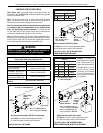
Secure all joints tightly using appropriate
tools and sealing compounds (ensure propane
resistant compounds are used in propane
applications).
All codes require a shut-off valve mounted
in the supply line. The orientation of the
shut-off valve should face the front. Figure
51 illustrates two methods for connecting the
gas supply. A sediment Trap is recommended
to prevent moisture and debris in the gas line
for damaging the valve.
WARNING
Electronic models of these appli-
ances are equipped with a three-
prong (grounding) plug utilized
in connecting the electronic
components to the junction box
in the lower compartment. This
grounding plug provides protec-
tion against shock hazard and
should be plugged directly into
the properly grounded three-
prong receptacle. DO NOT cut
or remove the grounding prong
from the plug.
FBK-250 Blower Kit
(See Figure 49 on page 25)-
An electrical outlet box is provided for the
installation of the FBK-250 forced air blower
kit. Electrical power must be provided to this
box to operate these blowers. Install the blower
kit according to the installation instructions
provided with the kit.
Note: The tab connecting the receptacles of
the outlet box must be broken in FBK-100 and
FBK-200 blower kit applications. See Figure 50.
Step 7. CONNECTING GAS LINE
Make gas line connections. All codes require a
shut-off valve mounted in the supply line. Figure
51 illustrates two methods for connecting the
gas supply. The flex-line method is acceptable
in the U.S., however, Canadian requirements
vary depending on locality. Installation must
be in compliance with local codes.
Step 6. WIRING - OPTIONAL FORCED AIR
BLOWER KIT
FBK-100 and FBK-200 Kits
(See Figure 48 on page 25) -
An electrical outlet box is provided for the
installation of the FBK-100, FBK-200 forced air
blower kits. Electrical power must be provided
to this box to operate these blowers. Install the
blower kits according to the installation instruc-
tions provided with the kits.
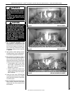
WARNING
Never use an open flame to
check for leaks.
TEST ALL CONNECTIONS FOR GAS LEAKS
(FACTORY AND FIELD):