


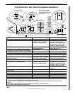
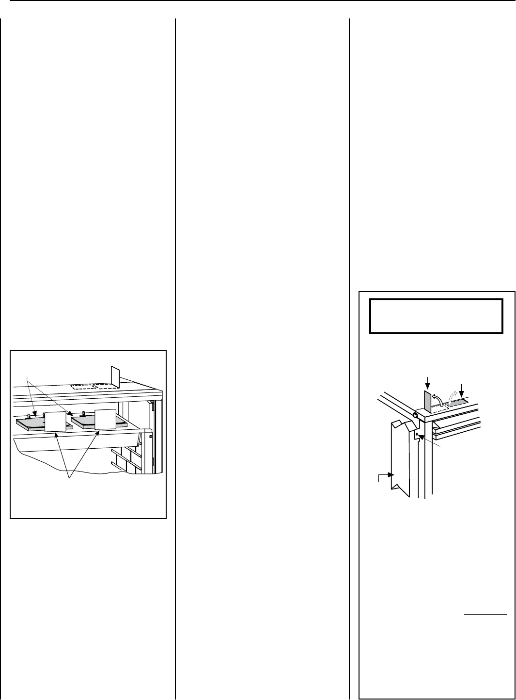
Pressure Relief
Plates
10
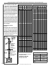
NOTE: DIAGRAMS & ILLUSTRATIONS ARE NOT TO SCALE.
LENNOX HEARTH PRODUCTS • MERIT
®
PLUS DIRECT VENT GAS FIREPLACES (MPD33/35/40/45) • INSTALLATION INSTRUCTIONS
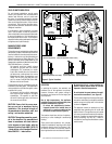
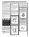
Side
Framing
Unit Nailing Flange
(No clearance to
combustible framing
is required.)
Unit Secured to Framing
by Nailing Flange
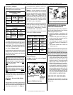
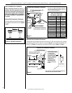
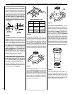
Header Spacing Top Standoffs
(two pairs on front edge of firebox top)
Lift up outer pair for
1/2" finish materials.
Lift up inner pair for
5/8" finish materials.
Left Side Front Corner of Fireplace Shown
(Right side requirements are the same)
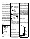
Note: The nailing flanges, combustible members
and screw heads located in areas directly adjacent
to the nailing flanges, are EXEMPT from the 1/2"
clearance to combustible requirements for the
firebox outer wrapper
. Combustible framing may be
in
direct contact with the nailing flanges and may
be located closer than 1/2" from screw heads and
the firebox wrapper in areas adjacent to the nailing
flanges. Frame the opening to the exact dimensions
specified in the framing details of this manual.
IMPORTANT!
Bend up the appropriate header spacing top
standoffs before installing the fireplace.
PRE-INSTALLATION STEPS
The appliance is shipped with all gas controls
and components installed and pre-wired.
Before installing the appliance, follow these
steps:
1. Remove the shipping carton.
2. Remove the shipping pad, exposing the front
glass door.
3. Open the two latches securing the glass
door (under the firebox floor). Remove the
door by tilting it outward at the bottom and
lifting it up. Set the door aside, taking care
to protect it from inadvertent damage. See
Removing Glass Panels on Page 32.
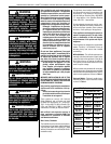
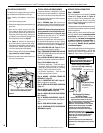
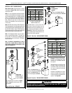
4. See Figure 11. Remove the top louvered
panel and locate the pressure relief plates.
Lift the pressure relief plates, and remove the
cardboard from beneath each plate (taking
care not to damage the white gasket).
5. Remove the log set from the firebox. Handle
logs carefully to prevent breakage.
6. Remove the embers and volcanic stone from
the control compartment.
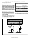
Figure 12
DETAILED INSTALLATION STEPS
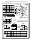
Step 1. FRAMING
Frame the appliance as illustrated in Figures
13 and 14 on Pages 10 and 11 (Figure 14
applies to corner framing installations only).
All framing details must allow for a minimum
clearance to combustible framing members as
shown in Table 5 on Page 8.
If the appliance is to be elevated above floor level,
a solid continuous platform must be constructed
below the appliance.
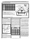
Headers may be in direct contact with the appli-
ance top standoff spacers when they are bent
up vertically, maintaining the 3" clearance to
the fireplace top, but must not be supported
by them or notched to fit around them. All
construction above the appliance must be
self-supporting. DO NOT use the appliance
for structural support.
Secure the fireplace to the side framing members
using the unit’s nailing flanges — one top and
bottom on each side of the fireplace front. See
Figure 12. Use 8d nails or their equivalent.
TYPICAL INSTALLATION SEQUENCE
The typical sequence of installation is outlined
below; however, each installation is unique and
may result in variations to the steps described.
See the pages referenced in the following steps
for detailed procedures.
Step 1. FRAMING (Page 10): Construct the
appliance framing. Position the appliance within
the framing and secure with nailing brackets.
IMPORTANT! Bend up the appropriate header
spacing standoffs for the drywall/finish mate-
rial thickness to be used (see Figure 60, page
32). Bend up the outer pair for 1/2" materials
and the inner pair for 5/8" materials.
Bend out the appropriate nailing flanges for
the drywall/finish material to be used. Nailing
flanges are provided for flush framing, 1/2-inch
and 5/8-inch framing depths (see Figure 12).
Step 2. ROUTING GAS LINE (Page 12): Route
gas supply line to appliance location.
Step 3. PREPARING APPLIANCE VENT COLLAR
(MPD-3530/4035/4540 models with combined
top/rear vent) (Page 13).
Step 4. INSTALLING VENT SYSTEM (Page 13):
Install the vent system and exterior termination.
Step 5. FIELD WIRING (Page 25).
a. Millivolt Appliances – Install the operat-
ing control switch (not factory provided). If
installing the optional forced air circulating
blower, bring in electrical service line.
b. Electronic Appliances – Field wire and
install operating control switch.
Step 6. WIRING - OPTIONAL FORCED AIR
BLOWER KIT (Page 26).
Step 7. CONNECTING GAS LINE (Page 26):
Make connection to gas supply.
Step 8. VERIFYING APPLIANCE OPERATION
(Page 27).
Step 9. INSTALL LOGS, VOLCANIC STONE,
AND GLOWING EMBERS (Page 28).
Step 10. INSTALLING GLASS DOOR ASSEM-
BLY (Page 32).
Step 11. BURNER ADJUSTMENTS (Page 32):
Adjust burner to ensure proper flame appear-
ance.
Step 12. HOOD INSTALLATION (Page 34).
Step 13. ATTACHING SAFETY-IN-OPERATION
WARNINGS (Page 35).
Figure 11
Remove cardboard before using appliance.
Take care not to damage white gasket.
NOTE: The nailing flanges, combustible
members, and screw heads in areas directly
adjacent to the nailing flanges are EXEMPT
from the 1/2" clearance to combustible
requirements for the firebox outer wrapper.
Combustible framing may be in direct contact
with the nailing flanges and may be located
closer than 1/2" from screw heads and the
firebox wrapper in areas adjacent to the
nailing flanges.
Frame the opening to the exact dimensions
specified in the framing details in this manual.
REMOVE
CAR
D
B
OAR
D
B
EFORE USING
REMOVE
CAR
D
B
OAR
D
B
EFORE USING