


NOTE: DIAGRAMS & ILLUSTRATIONS NOT TO SCALE.
4
Control
Compartment Access panel
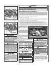
WARNING
Carbon monoxide poisoning:
early signs of carbon monoxide
poisoning are similar to the fl u
with headaches, dizziness and/or
nausea. If you have these signs,
obtain fresh air immediately. Turn
off the gas supply to the appliance
and have it serviced by a quali-
fi ed professional, as it may not
be operating correctly.
WARNING
Any safety guard or screen
removed for servicing the appli-
ance must be replaced prior to
operating the appliance.
WARNING
Children and adults should be
alerted to the hazards of high
surface temperatures. Use cau-
tion around the appliance to
avoid burns or clothing ignition.
Young children should be carefully
supervised when they are in the
same room as the appliance.
Note: An Optional Screen Heat
Guard for the glass is available
(see Page 14 for ordering infor-
mation).
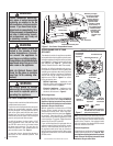
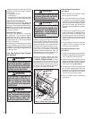
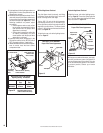
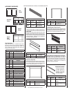
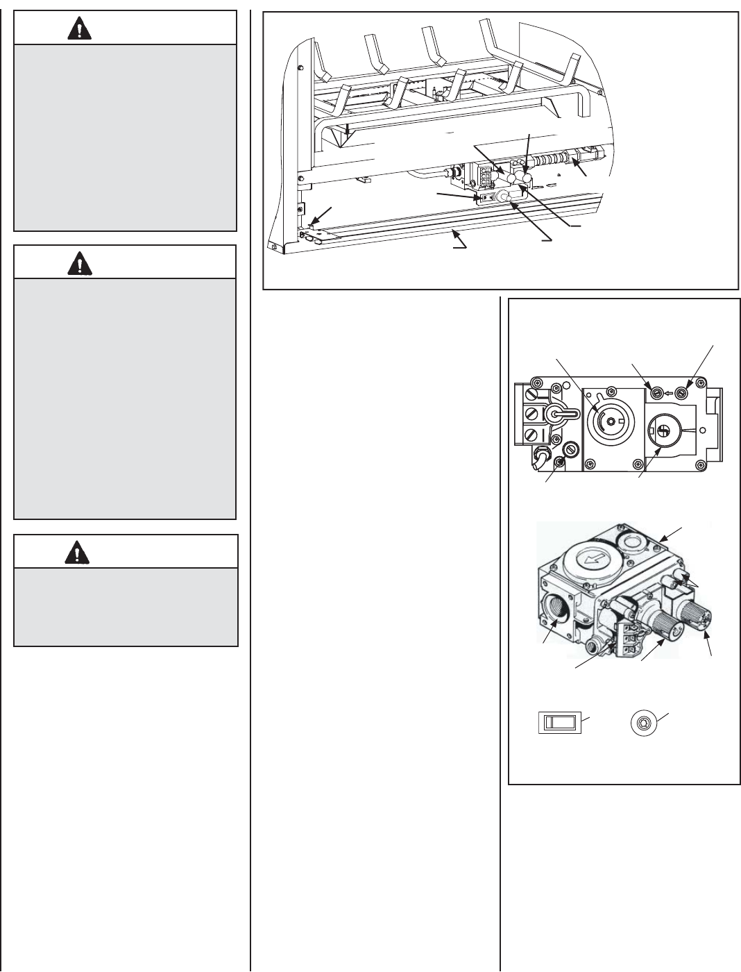
Gas Control Compartment Access
The gas controls can be found behind the control
compartment access panel.
To open the control compartment access panel,
actuate the spring-loaded magnetic catches
securing the panel. First, depress the outer top
right corner of the panel until the catch "pops"
the door free. Then, gently pull the door forward
until the left top corner "pops" free, allowing the
panel to swing out and down to open.
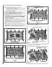
On millivolt systems, the piezo igniter, HI/LO
fl ame adjustment knob, and pilot and main
gas OFF/ON control knob are located below
the glass panel enclosure. The gas valve for
electronic systems is also located below the
glass enclosure panel. See Figure 1.
To ease door closure, depress the catches to
place them in their retracted position, then
close the door.
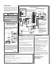
TPTH TP TH
Note: The piezo igniter and burner
OFF/ON switch are located below
glass panel (see Figure 1).
H
I
L
O
W
H
TPT
HT
P
T
P
I
L
O
T
P
I
L
O
T
O
N
it
O
F
F
IN
OUT
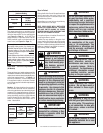
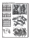
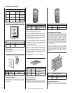
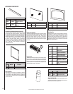
Manifold Pressure Tap
Inlet Pressure Tap
SIT Millivolt Gas Valve
Main Gas
Control Knob
OFF/PILOT/ON
HI/LO Variable
Flame Height
Adjustment
Gas
Outlet
Gas
Inlet
Pilot Adjustment
Screw
Terminals
TPTH,TP & TH
HI/LO Variable
Flame Height
Adjustment
Main Gas
Control Knob
OFF/PILOT/ON
Figure 2
OPERATION AND CARE OF YOUR
APPLIANCE
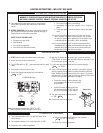
The standard controls for appliance operation
are located behind the hinged drop-down panel
below the appliance front glass enclosure panel
(see Figure 1). Optional control switches are
also available (see Page 12 - Remote Wall
Switch, Remote Control or Wall Thermostat).
Operation of millivolt and electronic gas con-
trol systems are different. Before lighting and
operating your appliance determine if you have
a millivolt or electronic appliance. Familiarize
yourself with the gas control valve that your
appliance uses. Refer to Figure 1 for access
to the gas control valve.
Millivolt Appliances - Appliances with
Millivolt systems will be fi tted with the gas
control valve shown in Figure 2.
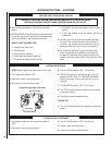
Electronic Appliances - Appliances with
electronic systems will be fi tted with the
electronic valve shown in Figure 3.
Millivolt Appliances -
To light millivolt appliances refer to the detailed
lighting instructions found on Page 15 . Millivolt
appliance lighting instructions may also be
found on the pull out lighting instruction labels
attached to the gas control valve.
Millivolt appliances are fi tted with an OFF/ON
Rocker Switch located behind the control
compartment access panel, below the appli-
ance front glass enclosure panel (see Figure 1
for location). Once the pilot is lit, the OFF/ON
rocker switch will control the appliance OFF/ON
burner operation. To operate: Toggle the switch
between its ON and OFF positions.
If your millivolt appliance is equipped with an
optional remote switch kit (wall switch, remote
control or wall thermostat) and the pilot is lit,
the appliance main burner may be turned on
and off using the optional switch. When using
an optional remote switch, turn off the standard
OFF/ON switch.
Electronic Appliances -
To light electronic appliances refer to the detailed
lighting instructions found on Page 16. Elec-
tronic appliance lighting instructions may also be
found on the pull out lighting instruction labels
attached to the gas control valve.
OFF/ON
(burner)
OFF
ON
IGNITER
Figure 1 - Gas Control Compartment Access
HI/LO (fl ame height
control knob)
OFF/PILOT/ON (gas control knob)
Gas Flex Line
Gas Valve
Piezo Igniter
OFF/ON Switch
Hinge Pin
Note:The gas supply
line must be installed
in accordance with
building codes by a
qualifi ed installer
approved and/or
licensed as requed
by the locality. In
the Commonwealth
of Massachusetts,
installation must
be performed
by a licensed
plumber or gas
fi tter.
Note: To prevent excessive resistance in burner
circuit (which can cause burner operation prob-
lems), only one burner control switch should be
wired to valve. Therefore, if an optional control
switch is installed, the standard Off/On switch
and wires should be removed.