


NOTE: DIAGRAMS & ILLUSTRATIONS NOT TO SCALE.
10
2. Light appliance (follow lighting procedure on
lighting label in control compartment or see
homeowners manual).
3. Allow the burner to operate for at least 15 min-
utes while observing the fl ame continuously
to ensure that the proper fl ame appearance
has been achieved (see Figure 13 ). If the
following conditions are present, adjust
accordingly.
• If flame appears weak or sooty, adjust
the air shutter, incrementally, to a more
open position until the proper fl ame
appearance is achieved.
• If fl ame stays lowered blue, adjust the
air shutter, incrementally, to a more
closed position until the proper fl ame
appearance is achieved.
4. Leave the control knob (off/pilot/on) in the
ON position and the burner OFF/ON switch
OFF (& remote switches, if applicable).
5. When satisfi ed that the burner fl ame appear-
ance is normal, close the lower control
compartment door.
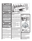
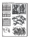
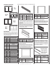
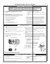
Adjustment Rod Positions
(when viewed from above)
Figure 14
Main Burner Factory Air Shutter
Opening Setting - All Models
Model Natural
Gas
Propane
Gas
MPD35ST
1/8”
3.2mm
1/4”
6.4mm
Increase Shutter Opening
In This Direction
Decrease Shutter Opening
In This Direction
Note - Burners are
omitted in this
view for clarity.
Orifi ce
Air Shutter
Adjusting
Rod
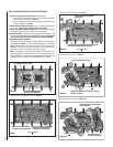
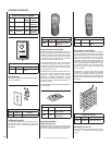
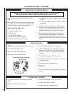
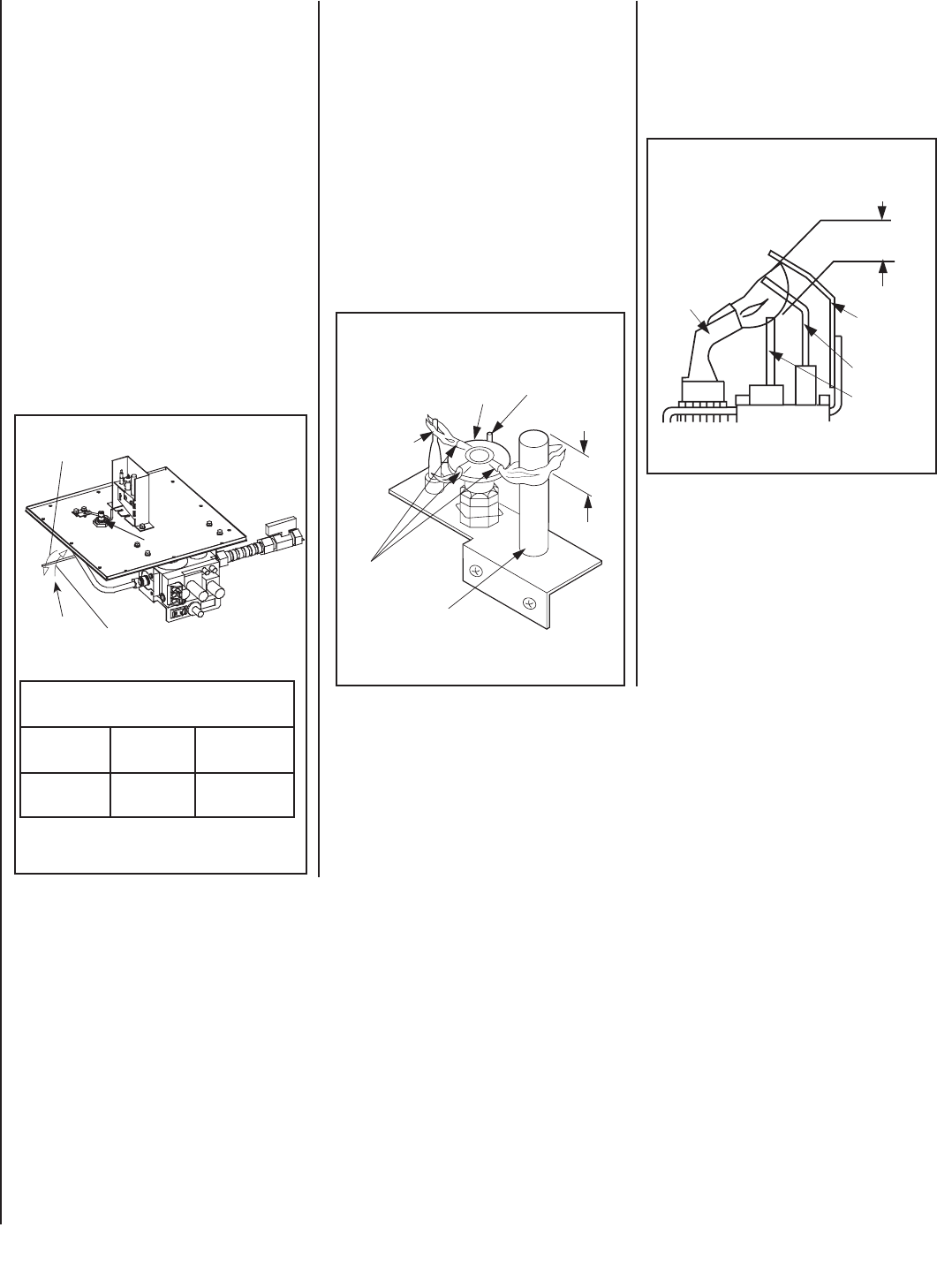
Electronic Appliance Checkout
To light the burner, refer to the lighting instruc-
tions on Page 16. Ensure the igniter lights the
pilot. The pilot fl ame should engulf the fl ame
sensor as shown in Figure 16.
Figure 16
3/8" to 1/2"
(9 -13 mm)
Ground
Electrode
Flame Rod
Hot Surface
Igniter
Proper Flame
Adjustment
Pilot
Nozzels
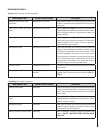
Millivolt Appliance Checkout
The pilot fl ame should be steady, not lifting
or fl oating. Flame should be blue in color with
traces of orange at the outer edge.
The top 3/8" (10 mm) at the pilot generator
(thermopile) and the top 1/8" minimum (tip)
of the quick drop out thermocouple should be
engulfed in the pilot fl ame. The fl ame should
project 1" (25 mm) beyond the hood at all three
ports. See Figure 15.
To light the burner, refer to the lighting instruc-
tions on Page 15.
ELECTRONIC PILOT ASSEMBLY
Proper Pilot Flame Appearance
Figure 15
Thermocouple
Thermopile
Pilot
Nozzels
MILLIVOLT PILOT ASSEMBLY
3/8" Min.
(9 mm)
Igniter Rod
Hood
Proper Pilot Flame Appearance
With proper care and maintenance, your appli-
ance will provide many years of enjoyment. If
you should experience any problem, fi rst refer
to the troubleshooting guide in this manual.
If problem persists, contact your Lennox
distributor.