


15
NOTE: DIAGRAMS & ILLUSTRATIONS ARE NOT TO SCALE.
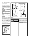
The outside air shutter should be fully open when
the fireplace is in use and completely closed
when the fireplace is not being used. Closing
it when not in use will prevent outside cold air
from entering the dwelling.
Operate the actuator through several cycles
including the closed position. Ensuring proper
operation and freedom of movement. Return
the actuator arm to the closed position.
Observe the individual tongues of flame on
the burner. Make sure all ports are open and
producing flame evenly across the burner. If
any ports are blocked, or partially blocked,
clean out the ports.
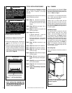
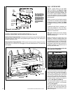
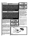
Electronic Appliance Checkout
To light the burner, turn ‘ON’ the OFF/ON switch
(located below valve) and turn the gas control
switch to the “ON” position. Ensure the igniter
lights the pilot. The pilot flame should engulf
the flame rod as shown in Figure 24.
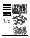
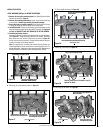
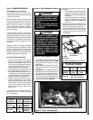
Step 8. INSTALL GRATE, VERMICULITE,
GLOWING EMBERS AND LOGS
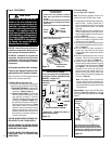
WARNING
•
DO NOT attempt to install the
logs until the appliance instal-
lation has been completed, the
gas line connected and tested
for leaks and the initial burner
operation has been checked
out.
•
The size and position of the log
set was engineered to give the
appliance a safe, reliable and
attractive flame pattern. Any
attempt to use a different log
set in the fireplace will void
the warranty and will result in
incomplete combustion, soot-
ing, and poor flame quality.
•
Logs get very hot and will
remain hot up to one hour
after gas supply is turned off.
Handle only when logs are
cool. Turn off all electricity
to the appliance before you
install grate and logs.
•
This appliance is not designed
to burn wood. Any attempt
to do so could cause irrepa-
rable damage to the appliance
and prove hazardous to your
safety.
•
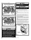
If logs are not installed
according to the log instal-
lation instructions, flame
impingement and improper
combustion could occur and
result in soot and/or excessive
production of carbon monoxide
(CO), a colorless, odorless,
toxic gas.
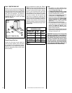
Outside Combustion Air Kits
Cat. No. Model No. Description
81L87 FOAK-4 Combustion Air Kit (w/duct)
81L88 FOAK-4LD Combustion Air Kit (w/o duct)
(ref. Form # 750,008M)
Outside Air Kits - Outside Air kits are avail-
able with duct (FOAK-4) and without duct
(FOAK-4LD) for use if outside combustion air
is required or desired. If model FOAK-4LD is
used it must be used in conjunction with locally
purchased, non-combustible Class 1 or Class
0 flexible duct.
Step 7. VERIFY APPLIANCE OPERATION
With gas line installed run initial system check-
out before closing up the front of the unit. Follow
the pilot lighting instructions provided in the
Care and Operation Instructions manual. For
piezo igniter location see Figure 20 on Page
14 (millivolt appliances only).
Note: The (pull-out) Lighting instructions label
can be found in the control compartment
(see Figure 20).
When first lighting the appliance, it will take
a few minutes for the line to purge itself of
air. Once purging is complete, the pilot and
burner will light and operate as indicated in
the instruction manual. Subsequent lightings
of the appliance will not require such purging.
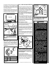
Inspect the pilot flame.
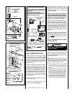
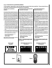
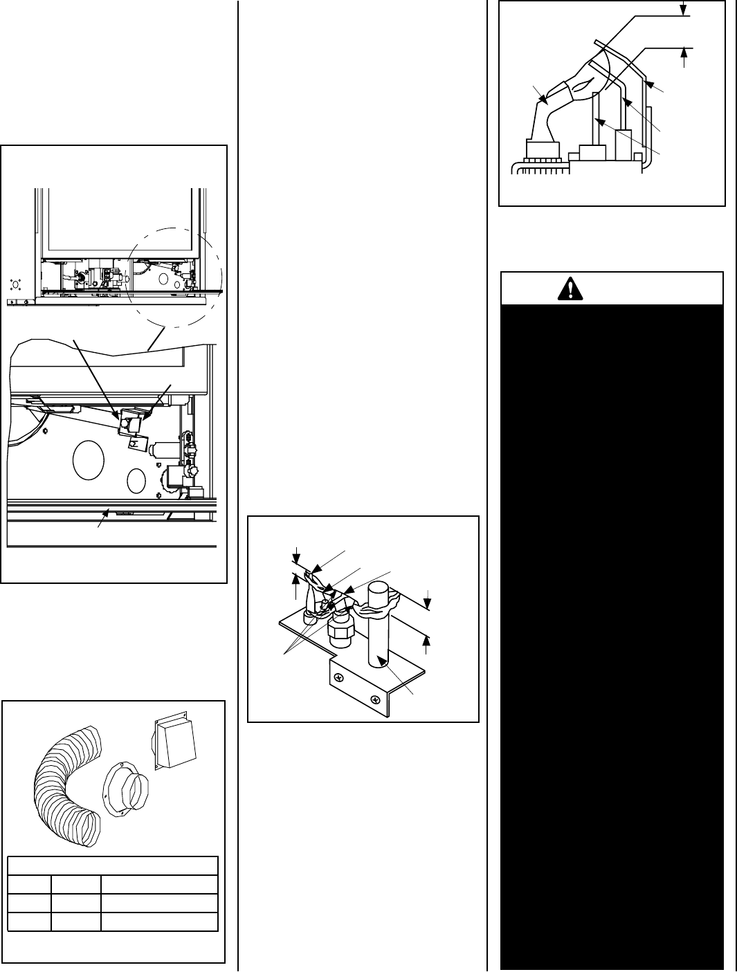
Millivolt Appliance Checkout
The pilot flame should be steady and, not lifting
or floating. Flame should be blue in color with
traces of orange at the outer edge.
The top 3/8" (10 mm) at the pilot generator
(thermopile) and the top 1/8" min (tip) of the
quick drop out thermocouple should be engulfed
in the pilot flame. The flame should project 1"
(25 mm) beyond the hood at all three ports
(Figure 23).
To light the burner; rotate the gas valve control
knob counterclockwise to the “ON” position
then turn “ON” the OFF/ON switch (installed at
Step 4, Page 12).
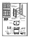
Figure 23
Proper Pilot Flame Appearance
Thermocouple
Thermopile
Pilot
Nozzels
3/8" Min.
(9 mm)
1/8" Min.
(3 mm)
Igniter Rod
Hood
Figure 24
3/8" to 1/2"
(9 -13 mm)
Ground
Electrode
Flame Rod
Hot Surface
Igniter
Proper Flame
Adjustment
Pilot
Nozzels
ELECTRONIC
Glass Front
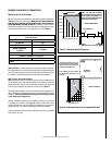
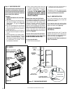
Figure 21
Control Compartment Access Panel
Outside Air Control Lever
with Stop Behind
Securing Screw
Outside Air Control Lever
and Securing Screw Location
Figure 22