


8
NOTE: DIAGRAMS & ILLUSTRATIONS NOT TO SCALE.
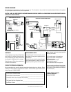
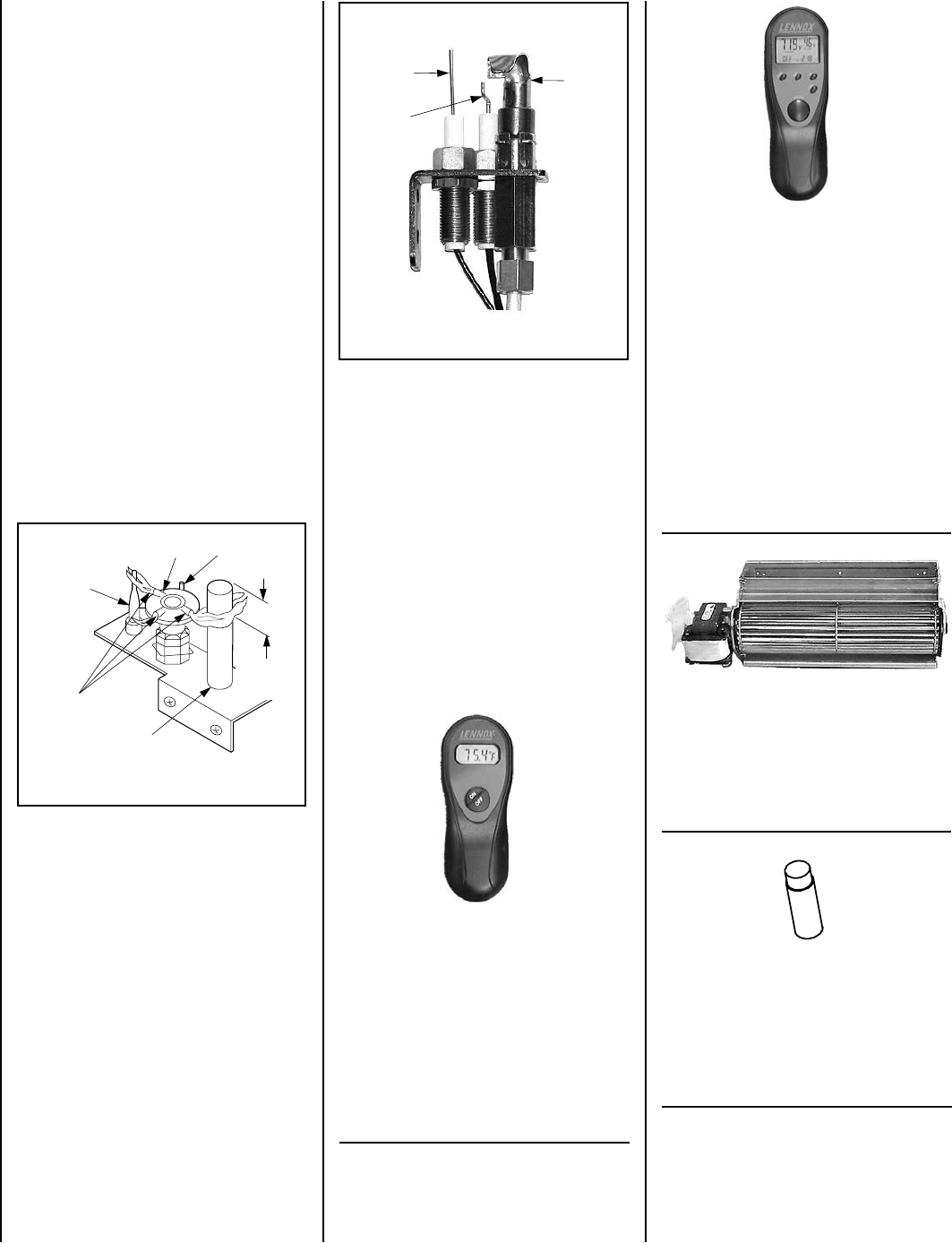
Figure 9
Figure 10
Glowing Embers (Rockwool) and Volcanic
Stones Placement
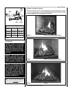
Refer to the detailed glowing embers placement
instructions provided in the LOG PLACEMENT
GUIDE accompanying this document.
Ceramic Panel Placement
Refer to the detailed ceramic panel placement
instructions provided in the LOG PLACEMENT
GUIDE accompanying this document.
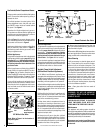
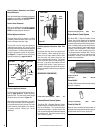
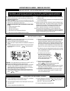
Millivolt Appliance Checkout
The pilot flame should be steady, not lifting
or floating. Flame should be blue in color with
traces of orange at the outer edge.
The top 3/8" (10 mm) at the pilot generator
(thermopile) and the top 1/8" min (tip) of the
quick drop out thermocouple should be engulfed
in the pilot flame. The flame should project 1"
(25 mm) beyond the hood at all three ports.
See Figure 9. To light the burner, refer to the
lighting instructions on pages 12 and 13.
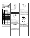
ACCESSORY COMPONENTS
Remote Control System (Standard) H0249 RCL
Standard Remote Control System
The Model RCL (Standard) Remote Control
System, features a simple On/Off control func-
tion for the fireplace. This model includes a
hand-held transmitter, a remote receiver with
wall-mount coverplate and all hardware required
to install the unit. The remote receiver can be
wall or hearth mounted.
Deluxe Remote Control System
The Model RCL-T (Deluxe) Remote Control
System has all of the features of the standard
system along with an added easy to read LCD
screen which presents access to many enhance-
ments, including; battery power level indicator,
timer, mode of operation, thermostatic display
including room temperature in either metric
of English units, flame indicator and clock.
Fully programmable, the Model RCL-T allows
for command over nearly all operational and
temperature variables, using the hand held
remote control transmitter.
Remote Control System (Deluxe) H0251 RCL-T
Forced Air Blower Kit
Single Speed H4678 LBLK-100
Forced Air Kit
The LBLK-100 blower provides constant velocity
forced air circulation.
MILLIVOLT
Thermocouple
Hood
Ignitor Rod
3/8" Min
(9 mm)
Thermopile
Pilot
Nozzels
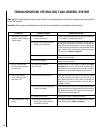
ELECTRONIC
Pilot
Hood
Sensor
Ignitor
Touch-Up Paint (Black) Kit 70K99 FTPK-B
Touch-Up Paint Kit
Repair of minor scratches and discoloration of
the appliance charcoal painted surfaces may be
accomplished with the touch-up paint kit.
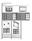
Installing Optional Decorative Style View
Doors
Decorative Style View doors are optional with
these fireplaces. When installing Style View
doors on any of these models remove, retain
and store away the bottom panel from the
control compartment accessway. The bottom
of the Style View doors provide coverage for
this area. If the doors are installed, the unit
mounted On/Off switch, if used, must be re-
located to the bracket provided with the door.
Refer to the detailed instructions provided with
the doors.
Electronic Appliance Checkout
To light the burner, refer to the lighting instruc-
tions on page 14 and 15. Ensure the ignitor
lights the pilot. The pilot flame should engulf
the flame sensor as shown in Figure 10.
With proper care and maintenance, your appli-
ance will provide many years of enjoyment. If
you should experience any problem, first refer
to the trouble shooting guide in this manual.
If problem persists, contact your Lennox
distributor.