


8
NOTE: DIAGRAMS & ILLUSTRATIONS ARE NOT TO SCALE.
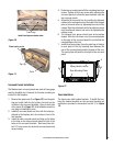
Facing and
Mantel -
Side View
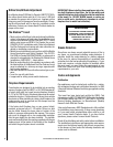
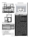
Facing and Mantel clearances
Note: Hearth protection to be min. 3/8” (10mm) thick non-
combustible or equivalent, with a k factor of .84.
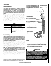
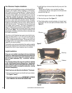
Insert Leveling
At each front and rear corner of the insert is an adjustable leg
provided to level the insert should the hearth of the fireplace
be uneven. To adjust the legs, loosen the two 5/32" allen head
screws, move the leg to the desired height and then tighten
the screws. Repeat these steps for each adjusting leg.
G 13”(330mm) 10”(254mm) 0”(0mm)
H 0”(0mm) 2”(21mm) 4”(102mm)
E
H
F
G
J
C
L
MANTEL
TRIM
Mantel
Trim
Hearth / Floor Protection
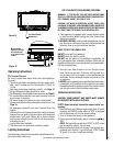
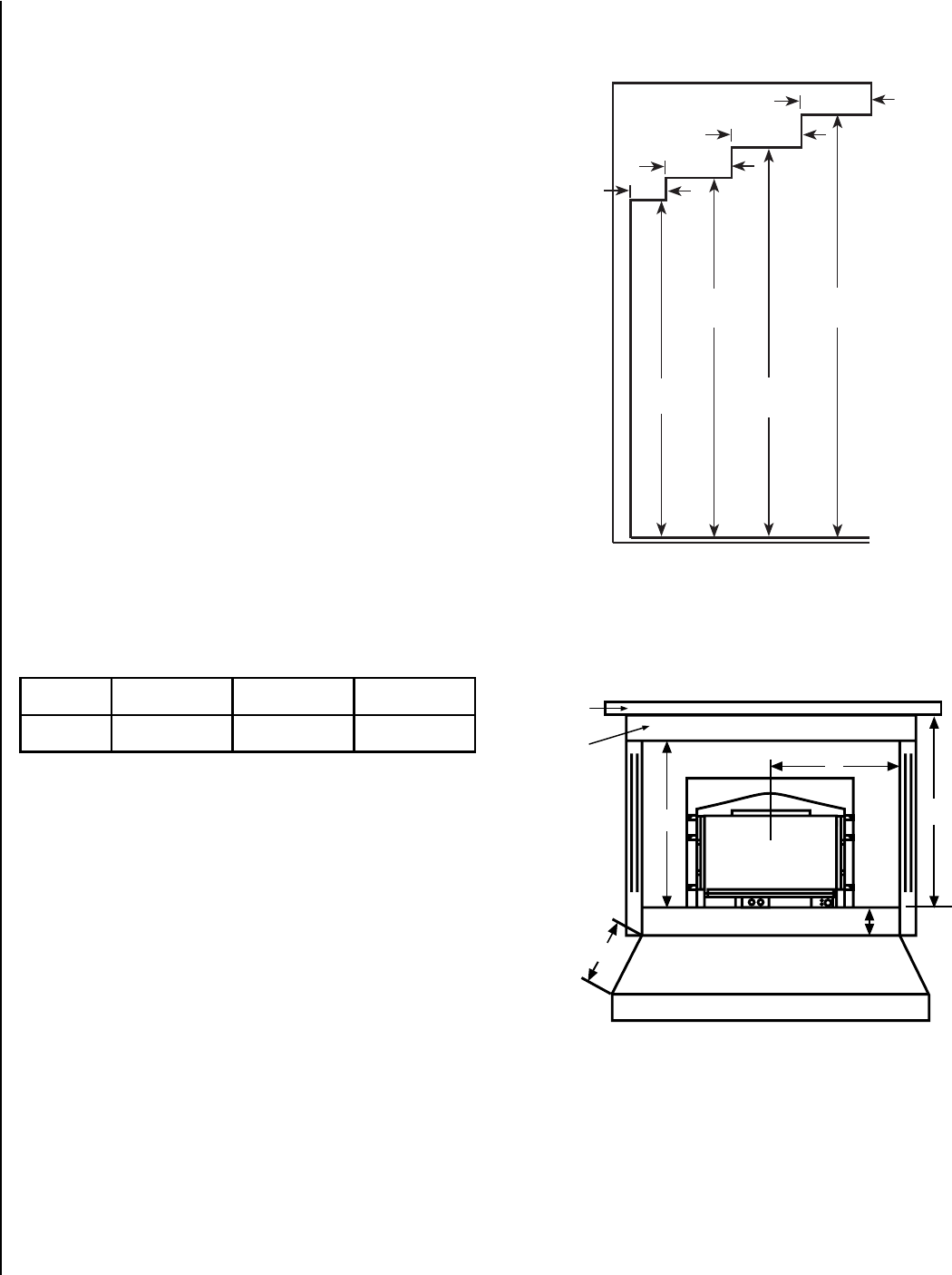
Minimum Clearances to Combustibles
Minimum clearances include any projections such as
shelves, window sills, mantels, spacers/standoffs or
surfaces to combustible construction etc. above the ap-
pliance. Paint or lacquer used to finish the mantel must
be heat resistant in order to avoid discoloration.
The letters below, E through J, correspond to Figure 4
showing minimum clearances required from the appliance
to combustibles and the minimum projection of the hearth
extension.
E = 31-1/2" (800 mm) from Top Facing to Bottom of
Insert
F = 25-1/2” (648 mm) from Center of Glass to Side Facing
or Side Wall
J = 39” (991 mm) from 10.5” (267 mm) Mantel to Bottom
of Insert
Hearth Protection
G = Minimum Hearth Protection from Front of Insert*
H = Vertical Distance from Insert Bottom to Combustible
Material.
3"/76mm
3"/76mm
3"/76mm
1-1/2”
38mm
31-1/2”
800mm
33-1/2”
851mm
36-1/2”
927mm
39-1/2”
1003mm
clearances
Figure 4
Figure 5