


5
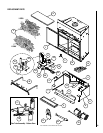
NOTE: DIAGRAMS & ILLUSTRATIONS NOT TO SCALE.
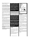
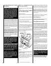
To Change Batteries
1. Remove cover on the backside of the trans-
mitter. Install 3 AAA batteries as shown inside
the cover and reattach the cover.
2. Once steps 1 thru 3 in OPERATION are
completed, receiver/valve and transmitter are
now ready. Press any button on transmitter
for recognition precess to occur between the
receiver/valve and transmitter.
3. Use functions as described in TRANSMIT-
TER section.
Troubleshooting
Step 1. Locate LED light on valve.
Step 2. LED will blink after every valid command
received by the transmitter; this is not an error.
Step 3. Failure codes may occur anytime after
pilot burner is lit.
Step 4. Sequence is failure code followed by
light not blinking for 4 seconds.
Step 5. In the event of multiple failure codes,
next failure code follows previous failure code
by approximately 3 seconds
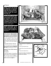
If an Error Code 3 is observed while perform-
ing the testing, complete the following:
Step 1. Make sure the spade connectors are
pushed all the way on. If the Error Code 3 is
still showing, then go to the next step.
Step 2. Switch the front two thermopile leads
with the back two. Be sure the lead is con-
nected to the spade with the white dot next to
it (
see Figure 4
). If the Error Code 3 is still
showing, replace the thermopiles.
If an Error Code 8 is observed while perform-
ing the testing, complete the following:
Step 1. Confirm that the valve is not in
REMOTE mode.
• If the valve is producing Error Code 8 and in
REMOTE mode, the valve is defective and
should be replaced.
• If the valve is in LOCAL mode and producing
Error Code 8, then go to the next step.
Step 2. Slide the Remote/Local switch to
REMOTE and reprogram valve recognition (re-
fer to in Operation section). The Error Code
will clear itself after approximately 1 1/2 min-
utes and return to normal operation.
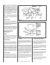
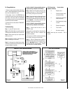
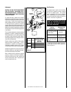
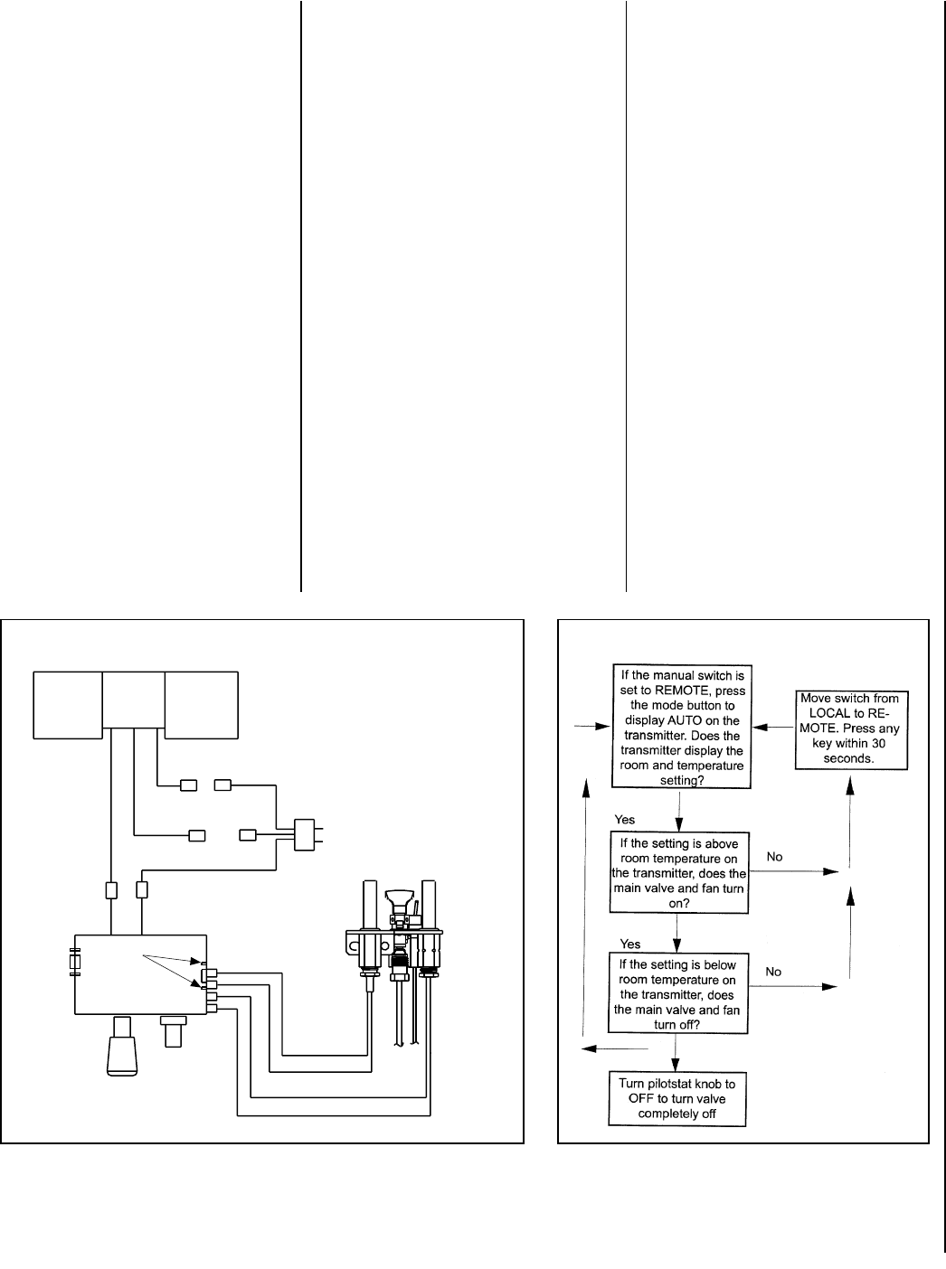
COMFORT VALVE WIRING DIAGRAM
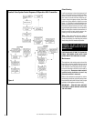
AUTO PATH DIAGRAM
Figure 4
Figure 5
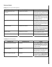
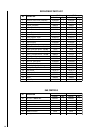
LED Failure Code Service Action
(Number Of Blinks)
8 Replace valve
7 Confirm stepper motor
connection exists
5 Confirm fan connection
exists and works
4 Confirm gas type; jumper
in place
3 Replace thermopiles
2 Turn fan ON
1 No action required
NOTE: Some keys are not active. This is
normal.
BLOWER
WHITE
BLACK
GREEN
BLACK
GREEN
F
M
F
F
M
RED
WHITE
RED
WHITE
VALVE
F
WHITE
White
Dots
CAUTION: LABEL ALL WIRES PRIOR TO
DISCONNECTION WHEN SERVICING CONTROLS.
WIRING ERRORS CAN CAUSE IMPROPER AND
DANGEROUS OPERATION. VERIFY PROPER
OPERATION AFTER SERVICING.