


NOTE: DIAGRAMS & ILLUSTRATIONS ARE NOT TO SCALE.
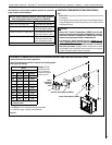
25
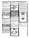
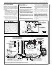
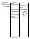
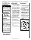
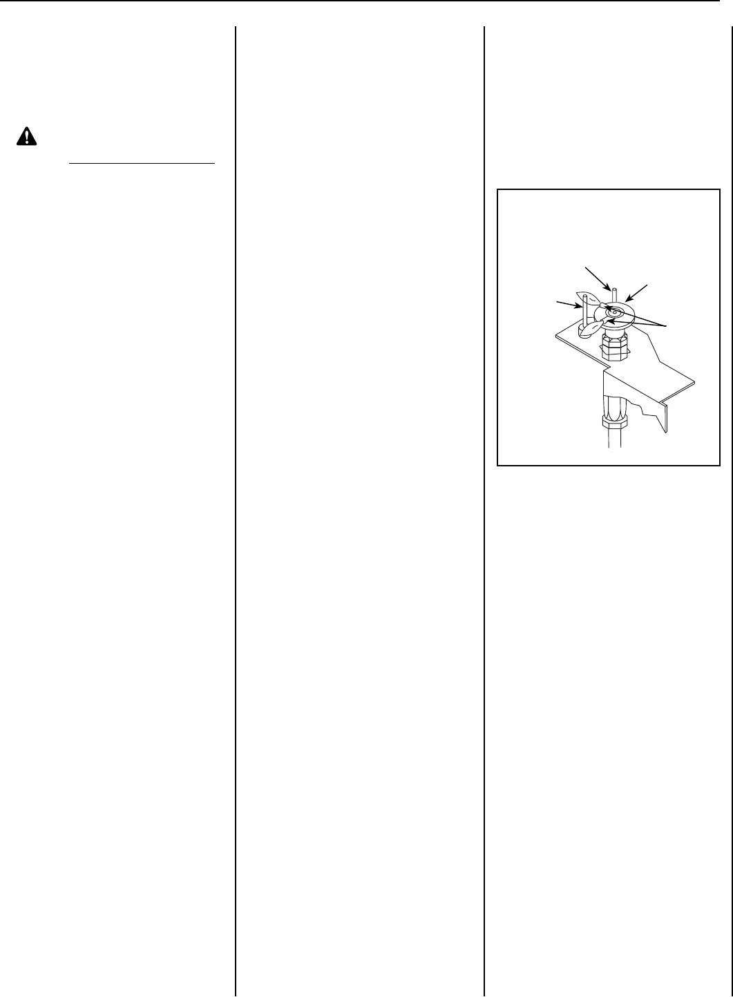
Flame
Sensor
Pilot
Nozzels
Igniter
Rod
Pilot Hood
PILOT ASSEMBLY
Proper Pilot Flame Appearance
Figure 38
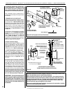
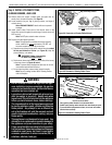
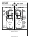
Step 7. INSTALL FIREBOX
LINER PANELS
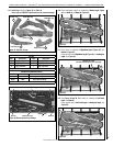
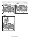
Install the ceramic or porcelain rebox liner
panels per the instructions provided in the kit
(ref. document P/N 506019-21).
NOTICE: Liner panels must be
installed before operating fireplace.
Step 8. VERIFY APPLIANCE
OPERATION
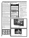
Turn on the burner, then observe the individual
tongues of ame on the burner.
Make sure all ports are open and producing
ame evenly across the burner.
If any ports are blocked (or partially blocked),
clean out the ports.
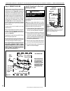
With the gas line installed, run initial system
checkout before closing up the front of the
unit. Follow the pilot lighting instructions pro-
vided in the Care and Operation Instructions.
Note: Lighting instructions also can be
found on the lighting label tied to the
bracket above the gas valve. To access
the tag, reach into the right side opening
(see Figure 37 on Page 24).
When first lighting the appliance, it will take a
few minutes for the line to purge itself of air.
Once purging is complete, the pilot and burner
will light and operate as indicated on Page 30.
Subsequent lighting of the appliance will not
require such purging.
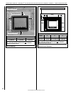
Inspect the pilot flame (remove logs, if neces-
sary, handling carefully).
Appliance Checkout
To light the burner, refer to the lighting in-
structions in the Care and Operation Instruc-
tions or the lighting label tied to the bracket
above the gas valve (behind the right panel).
Make sure the igniter lights the pilot. The
pilot flame should engulf the flame sensor, as
shown in Figure 38.
LENNOX HEARTH PRODUCTS • MONTEBELLO
®
SEE-THROUGH DIRECT-VENT GAS FIREPLACES (LSM40ST-N / LSM40ST-P) • INSTALLATION INSTRUCTIONS