


14
NOTE: DIAGRAMS & ILLUSTRATIONS ARE NOT TO SCALE.
LENNOX HEARTH PRODUCTS • MONTEBELLO
®
SEE-THROUGH DIRECT-VENT GAS FIREPLACES (LSM40ST-N / LSM40ST-P) • INSTALLATION INSTRUCTIONS
Step 3. INSTALL VENT SYSTEM
General Information
These instructions should be used as a
guideline and do not supersede local codes
in any way. Install venting according to lo-
cal codes, these instructions, the current
National Fuel Gas Code (ANSI-Z223.1) in
the USA or the current standards of CAN/
CSA-B149.1 in Canada.
Ensure clearances are in accordance with
local installation codes and the requirements
of the gas supplier.
Dégagement conforme aux codes d'in-
stalla tion locaux et aux exigences du
foumisseunde gaz.
Use only approved venting components. See
“Approved Vent Components” on Page 2.
These fireplaces must be vented
directly to the outside.
The vent system may not service multiple ap-
pliances and must never be connected to a ue
serving a solid fuel burning appliance.
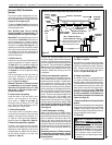
The vent pipe is tested to be run inside an
enclosed wall (such as a chase). There is no
requirement for inspection openings in the en-
closing wall at any of the joints in the vent pipe.
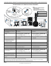
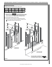
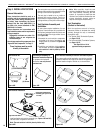
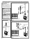
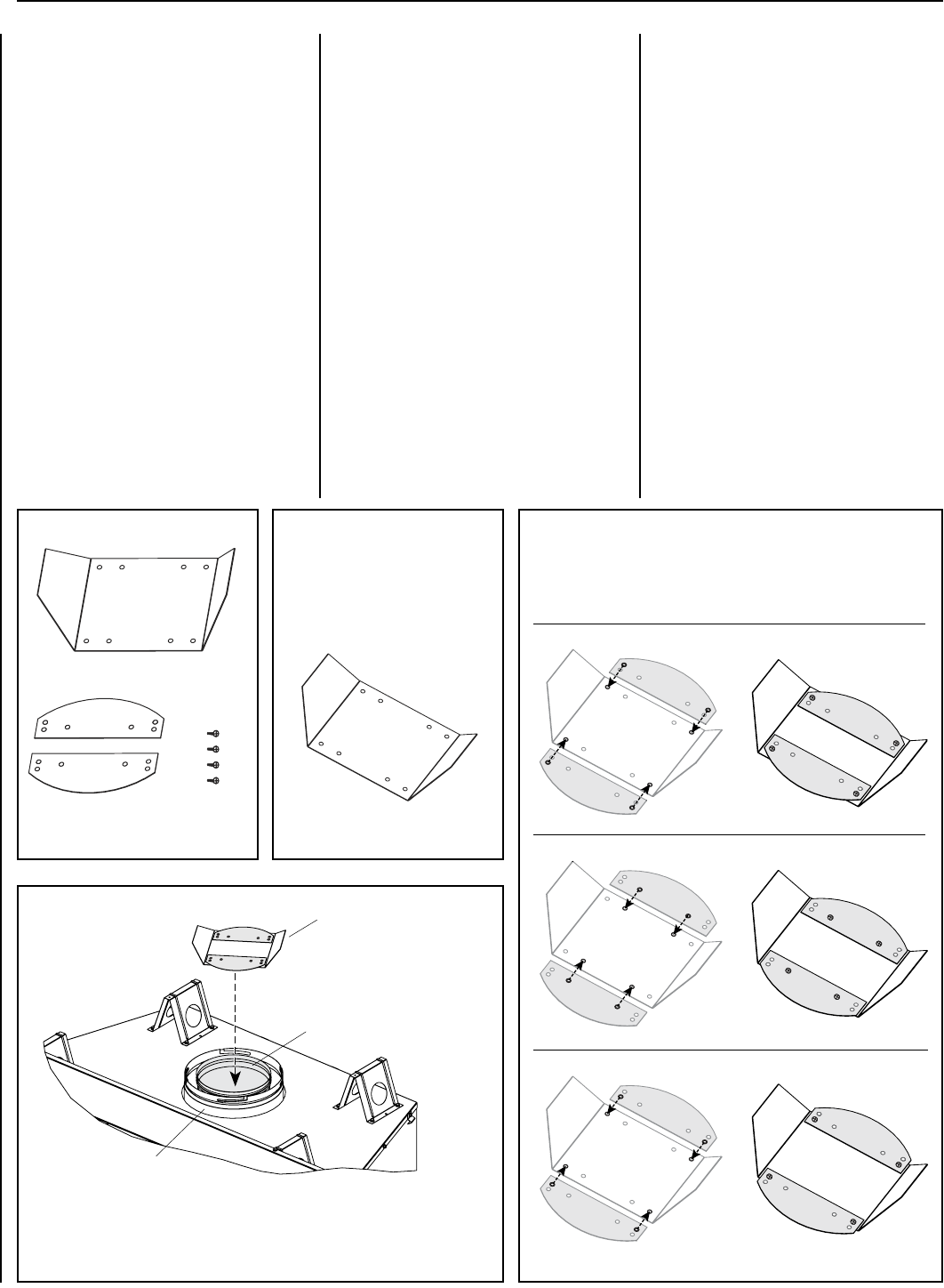
Vent Restrictor Assembly and
Installation
All vent systems require installation of a vent
restrictor. A vent restrictor kit is provided with
the replace (packaged inside the rebox) and
includes one base, two wings, and four screws
(see Figure 16A).
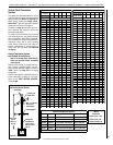
1. Assemble the vent restrictor components
according to the type of termination and
length of vent run, as shown in Figures 16B
and 16C.
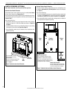
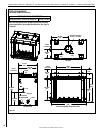
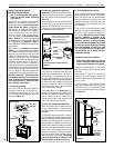
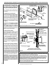
2. Install the vent restrictor in the appliance
top flue outlet, as shown in Figure 16D. The
vent restrictor is held in place by friction
only.
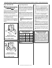
Note: When possible, install the vent
restrictor through the top of the appliance
vent outlet BEFORE installing the vent
system. (It is possible to install the vent
restrictor from inside the firebox after vent
system installation; however, doing so
requires removing the firebox baffle.)
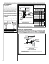
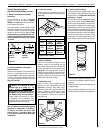
Vent Termination
(Vertical or Horizontal)
With the appliance secured in framing,
determine whether to terminate the venting
vertically (through the roof) or horizontally
(through the wall).
• For Vertical (Roof) Termination Systems,
see Pages 15–18.
• For Horizontal (Wall) Termination Systems,
see Pages 19–22.
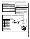
See Page 34 for a list of
approved venting components.
Assembly for vertical termination with 11–40 ft vertical runs:
Assembly for vertical termination with 6–10 ft vertical runs:
Assembly for vertical termination with 41–60 ft vertical runs:
Vent Restrictor Kit
(1) Vent Restrictor Base
(2) Wings (4) Screws
Vent Restrictor Assembly for Vertical Termination Systems
For systems with vertical termination, use the four provided
screws to attach the two wings to the base in the applicable
position based on length of vertical run, as shown below.
Vent Restrictor Assembly for
Horizontal Termination Systems
For systems with horizontal
termination, use only the vent
restrictor base.
Figure 16D
Install applicable vent restrictor assembly (per Figures 16B and 16C)
into inner collar of appliance vent outlet.
Note: The vent restrictor is held in place by friction only.
Applicable Vent Restrictor
Assembly (per Figures 16B
and 16C)
Appliance Vent Outlet
Inner Collar
~
~
Vent Restrictor Installation
Figure 16A Figure 16B
Figure 16C