


NOTE: DIAGRAMS & ILLUSTRATIONS ARE NOT TO SCALE.
30
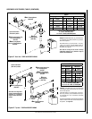
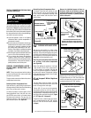
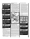
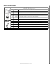
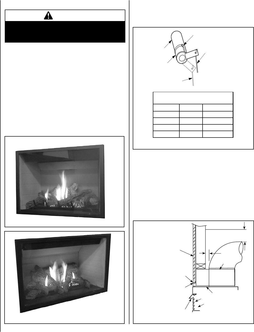
Main Burner Factory Air Shutter
Opening Setting - Inches (millimeter)
Model Nat.Gas Propane Gas
LMDVT-3328 1/16 (1.58) 1/4" (6.35)
LMDVR-3328 1/16 (1.58) 1/4" (6.35)
LMDV-3530 1/16(1.58) 5/16" (7.94)
LMDV-4035 1/8 (3.18) 3/8" (9.53)
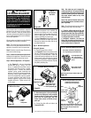
Adjustment
Rod Up
(Fully Open
Position)
Air Shutter
Adjustment Rod Down min.
air opening position)
Burner
Tube
Adjustment Set-Screw
Figure 60 - Burner Air Shutter Adjustment
Ref. Air shutter Patent:
U.S. Pat. 5,553,603
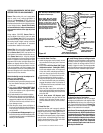
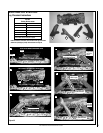
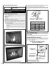
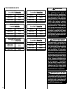
Figure 58- Burner Flame Appearance Model LMDV-3328 & LMDV-3530
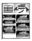
Figure 59 - Burner Flame Appearance Model LMDV-4035
CAUTION
The air shutter door and nearby appliance surfaces are
hot. Exercise caution to avoid injury while adjusting
flame appearance.
Burner Air Shutter Adjustment Procedure
1. Locate adjustment rod and adjust air shutter to the standard setting
as shown in
Figure 60 (adjustment rod is located in the lower control
compartment).
Note: Move the adjustment rod down to decreases air and up to
increases.
2. Light appliance (follow lighting procedure on lighting label in control
compartment or see homeowners manual).
3. Allow the burner to operate for at least 15 minutes while observing the
flame continuously to ensure that the proper flame appearance has
been achieved (see
Figures57 or 58). If the following conditions are
present, adjust accordingly.
• If flame appears weak or sooty, adjust the air shutter, incremen
-
tally, to a more open position until the proper flame appearance
is achieved.
• If flame stays lowered blue, adjust the air shutter, incrementally,
to a more closed position until the proper flame appearance is
achieved.
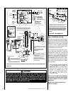
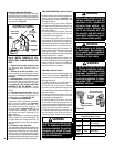
Step 11. HOOD INSTALLATION
(Refer to Figure 61) All of these appliances must have hoods installed
prior to operating.
Install hood by sliding it into the slots on the lower edge of the cabinet top
.
FINISHING REQUIREMENTS - Wall Details
Complete finished interior wall. To install the appliance facing flush with
the finished wall, position framework to accommodate the thickness of
the finished wall (
Figure 61).
See Page 4 for Cold Climate Insulation
and Page 7 for Clearances
Burner Air Shutter Adjustment Procedure
4. Leave the control knob (off/pilot/on) in the ON position and the burner
OFF/ON switch OFF (& remote switches, if applicable).
5.
When satisfied that the burner flame appearance is normal, re-install
the lower control compartment door then proceed to finish the instal
-
lation.
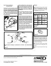
Combustible Finished
Wall Materials
Top of Appliance
Combustible material may
touch the appliance top
Louvers
Top of Door Frame
Hood must be installed as shown.
3"
(76 mm)
This Area Must
Remain Clear of
Combustible
Materials
1 in. Min.
(25 mm)
Drywall Bracket / Spacer
Top Spacers
Figure 61 - Combustible Wall Framing