


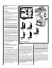
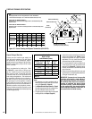
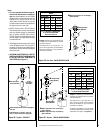
NOTE: DIAGRAMS & ILLUSTRATIONS ARE NOT TO SCALE.
10
C
Back wall of chase/enclosure
(including any finishing materials)
a
Inches
(millimeters)
LMDV and LMDVR units
D
E
F
A
B
LMDV and LMDVT units
7 1/4 (184)
b
Note-
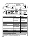
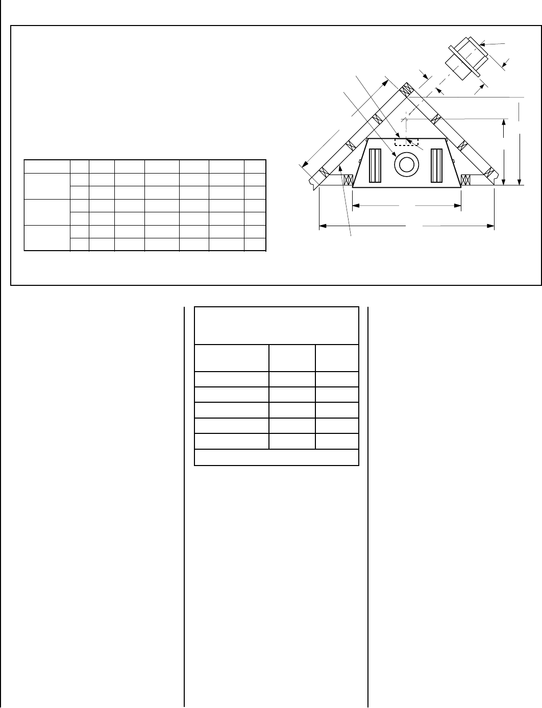
Venting requirments for rear vent applications in corner installations -
• The horizontal vent length "a" to "b" must not exceed 28 inches (711 mm).
LMDVT-3328 and LMDVR-3328 Models -
Dimension A to F occur when one 45 degree elbow is connected directly to the
appliance collar.
LMDVT-3530 and LMDVR-4035 Models -
Dimension D and F occur when one 45 degree elbow is connected directly to the
appliance collar.
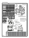
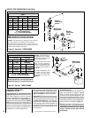
FIREPLACE FRAMING SPECIFICATIONS
Never use galvanized or plastic pipe. Refer
to
Table 9 for proper sizing of the gas sup-
ply line, if black iron pipe is being used. Gas
lines must be routed, constructed and made
of materials that are in strict accordance with
local codes and regulations. We recommend
that a qualified individual such as a plumber or
gas fitter be hired to correctly size and route
the gas supply line to the appliance. Installing
a gas supply line from the fuel supply to the
appliance involves numerous considerations of
materials, protection, sizing, locations, controls,
pressure, sediment, and more. Certainly no one
unfamiliar and unqualified should attempt sizing
or installing gas piping.
Schedule 40
Black Iron Pipe
Inside Diameter (Inches)
Schedule 40 Pipe
Length (feet)
Natural
Gas
Propane
Gas
0-10 1/2 3/8
10-40 1/2 1/2
40-100 1/2 1/2
100-150 3/4 1/2
150-200 3/4 1/2
Table 9
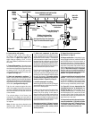
• A pipe joint compound rated for gas should be
used on the threaded joints.
Ensure propane
resistant compounds are used in propane
applications. Be very careful that the pipe
compound does not get inside the pipe.
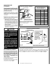
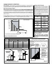
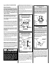
• It is recommended to install a sediment trap
in the supply line as close as possible to the
appliance (see
Figure 48 ). Appliances using
Propane should have a sediment trap at the
base of the tank.
• Check with local building official for local code
requirements (i.e. are below grade penetrations
of the gas line allowed?, etc).
IMPORTANT: If propane is used, be aware that
if tank size is too small (i.e. under 100-lbs, if
this is the only gas appliance in the dwelling.
Ref. NPFA 58), there may be loss of pressure,
resulting in insufficient fuel delivery (which
can result in sooting, severe delayed ignition
or other malfunctions). Any damage resulting
from an improper installation, such as this, is
not covered under the limited warranty.
Proper Sizing of Gas Line
Properly size and route the gas supply line
from the supply regulator to the area where
the appliance is to be installed per require
-
ments outlined in the National Fuel Gas Code,
NFPA 54 - latest edition (USA) or B149 - latest
edition (Canada).
Notes:
• All appliances are factory-equipped with a
flexible gas line connector and 1/2 inch shutoff
valve (see
Figure 48 on Page 24 ).
• See
Massachusetts Requirements on Page 4
for additional requirements for installations in
the state of Massachusetts in the USA.
• The gas supply line should Not be connected
to the appliance until
Step 6 (Page 24 ).
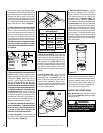
Figure 15 - Corner Framing with Square Termination (SV4.5HT-2)
.oNledoM A B C D E F
.ni 8/133 2/184 61/543 61/371 4/142 5
mm 148 2321 278 734 616 721
.ni 8/153 2/175 8/504 61/391 4/382 8/16
mm 298 1641 2301 784 037 651
.ni 8/104 61/316 23/1134 61/391 61/1103 8/77
mm 9101 4551 1011 784 977 002
LMDVT-3328
LMDVR-3328
LMDV-3530
LMDV-4035