


15
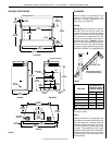
NOTE: DIAGRAMS & ILLUSTRATIONS ARE NOT TO SCALE.
LENNOX MERIT
®
SERIES B-VENT GAS FIREPLACES • 36" LMBV MODELS • INSTALLATION INSTRUCTIONS
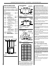
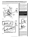
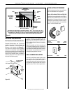
Step 5. All Millivolt Systems – Attach
manometer to the manifold side pressure
test fitting and verify manifold pressure
reads 3.5 inches water column (0.87 kPa) for
natural gas, and 10.0 inches water column
(2.49 kPa) for propane gas.
Step 6. Refer to Figure 25 and remove the
pilot hood assembly to access the hexed pilot
orifice. Remove and replace the orifice with
the one provided with the kit.
Electronic Appliances
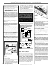
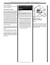
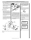
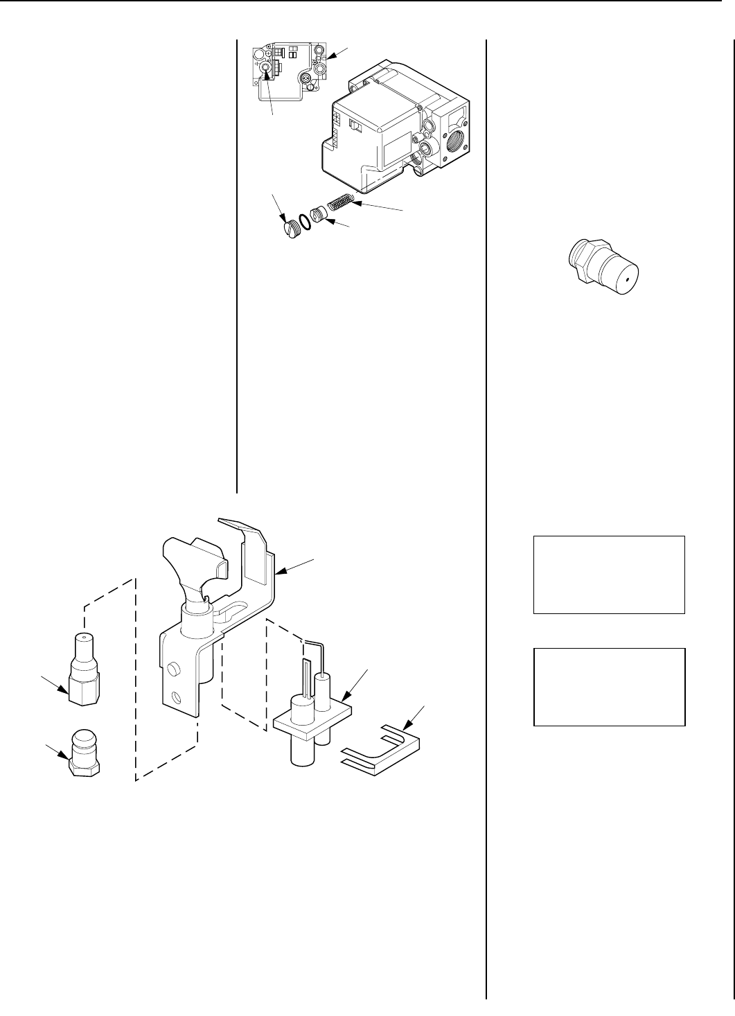
Step 7. Honeywell Electronic Valves - See
Figure 27 and the instructions provided
with the kit. Remove the slotted cap screw,
o-ring, pressure-regulating adjusting screw
and spring. Retain all parts for possible later
use. Install new components from the kit.
Black cap and red spring for propane gas
units. Silver cap and stainless steel spring
fro natural gas units.
Before installing the cap, attach manometer
to the manifold side pressure test fitting
and adjust screw until pressure reads 3.5
inches water column (0.87 kPa) for natural
gas, and 10.0 inches water column (2.49
kPa) for propane gas.
Figure 26
Figure 27
Figure 28
When reinstalling the ignitor assembly,
use extreme care to prevent damage and
breakage. Do not apply any leverage to
the ignitor assembly while restoring the
retainer clip to its original position.
All Models
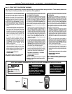
Step 8. Unscrew the orice from the manifold
and replace it with the one provided with the kit,
#42 (0.0935) for natural gas units and (0.058)
for propane (see Figure 28 ).
Figure 29
Step 11. Turn on gas supply and test for gas
leaks.
Step 9. Reassemble all removed components
by reversing the procedures outlined in the
preceding steps. Use pipe joint compound or
Teon tape on all pipe ttings before installing
(ensure propane resistant compounds are used
in propane applications, do not use pipe joint
compounds on are ttings). Check for leaks
(refer to page 8, Step 6).
Step 10. Attach appropriate conversion kit
label (see Figure 29 ) next to the rating plate
on the appliance.
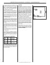
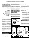
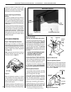
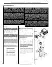
See Figure 26 and replace the pilot orifice
as follows: Remove the ignitor assembly
retainer clip, and carefully remove the ignitor
assembly.Exercise extreme care to prevent
damage to or breakage of the ignitor as-
sembly. Remove the screw securing the
pilot assembly to its mounting bracket. Back
off the are nut at the end of the pilot gas
line to free the pilot assembly from the gas
line. Remove the pilot orifice and replace it
with the one provided with the conversion
kit. Reinstall the pilot assembly by reversing
the steps detailed here.
Note: If the ignitor assembly is damaged, a replacement kit is available; order Catalog Number 87L54.
Retaining
Clip
Ignitor
Assembly
Pilot
Assembly
Pilot
Orifice
Flare Nut
THIS APPLIANCE HAS BEEN CONVERTED TO:
NATURAL GAS
INPUT BTU/HR – 24,000
MANIFOLD PRESSURE – 3.5"
ORIFICE SIZE – #42 (0.0935)
THIS APPLIANCE HAS BEEN CONVERTED TO:
PROPANE/LPG
INPUT BTU/HR – 24,000
MANIFOLD PRESSURE – 10"
ORIFICE SIZE – (0.058)
Spring
Adjusting
Screw
Slotted
Cap
PSI
OFF
I
ON
CONTROL
IGNITE
Manifold
Pressure
Test Port
Inlet Pressure Test Port