


13
NOTE: DIAGRAMS & ILLUSTRATIONS ARE NOT TO SCALE.
LENNOX MERIT
®
SERIES B-VENT GAS FIREPLACES • 36" LMBV MODELS • INSTALLATION INSTRUCTIONS
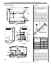
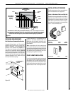
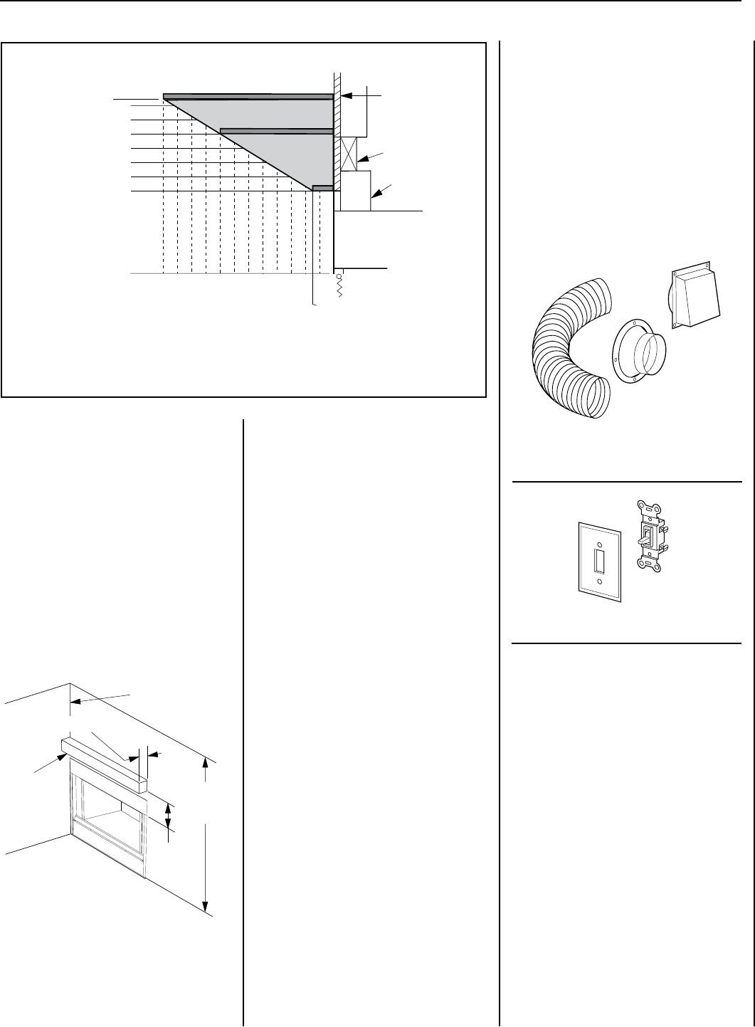
Figure 22
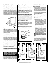
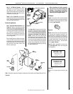
INSTALLATION ACCESSORIES
The following accessory items are available for
use in the installation of this appliance.
Outside Air Kits Models FOAK-4 and FOAK-4LD
Outside Air kits are available with duct (FOAK-4)
and without duct (FOAK-4LD) for use if outside
combustion air is required or desired. If model
FOAK-4LD is used it must be used in conjunc-
tion with locally purchased, non-combustible
Class 1 or Class 0 exible duct.
Wall Switch Kit 85L87 FWSK
Outside Combustion Air Kits
(with duct) 81L87 FOAK-4
(without duct) 81L88 FOAK-4LD
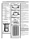
Figure 23
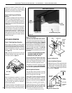
64"
(1626 mm)
Min. to
Ceiling
14-1/2" Min.
(368 mm)
0" (0 mm) Clearance
to Combustible
Side Wall
Max. Projection 12" (305 mm)
Combustible
Mantel
Fireplace
Opening
Spacer
Finished
Wall
Header
123456789
1011
12
8
9
10
11
12
Combustible
Mantel Clearances
Inches
Min. Height of
Mantel Above
Fireplace
Opening
Max.Length of Mantels
0
0
1-1/2
13
14
14-1/2
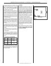
Three mantels are shown (dark gray elongated rectangles) - one, 1-1/2 in. long at a min. of 8 in.
above the fireplace opening; the second, 8 in. long at a min. of 12 in. above the fireplace opening;
and the third, 12 in. long at a min. of 14-1/2 in. above the fireplace opening; for any mantels
between these three in length, they must be located within the lighter gray shaded area.
A hearth extension is not required with this
appliance. Any hearth extension used is for
appearance only and does not have to con-
form to standard hearth extension installation
requirements.
Note: Combustible wall finish materials and/
or surround materials must not be allowed to
encroach the area defined by the appliance front
face (black sheet metal). Never allow combus-
tible materials to be positioned in front of or
overlapping the appliance front face.
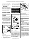
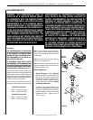
COLD CLIMATE INSULATION
If you live in a cold climate, seal all cracks around
your appliance with noncombustible material
and wherever cold air could enter the room. It
is especially important to insulate outside chase
cavity between studs and under oor on which
appliance rests, if oor is above ground level.
FINISHING REQUIREMENTS
Wall Details and Combustible Mantels
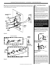
Complete finished interior wall. To install the
appliance facing ush with the nished wall,
position framework to accommodate the
thickness of the finished wall (Figure 22 ).
This figure also indicates vertical installation
clearances to combustible mantels. Figure 23
also shows an example of a combustible mantel
shelf projecting a maximum of 12" (305 mm)
from the wall, and which must be installed a
minimum distance of 14-1/2" (368 mm) from
the top of the firebox opening.