


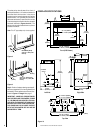

NOTE: DIAGRAMS & ILLUSTRATIONS NOT TO SCALE.
9
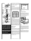
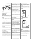
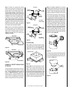
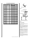
CHIMNEY 30° OFFSET THROUGH FLOOR
OR CEILING
It may be necessary to assemble the chimney at
30° when passing through the floor or ceiling
area. Use the F10FS30-2 firestop spacer as
shown in
Figures 23 and 24
. Support the
chimney at floor or ceiling penetration with a
FTF10 stabilizer if distance of chimney below
ceiling is 10' or more. Maintain 2" minimum air
space to combustibles from chimney sections.
F10FS30-2
Firestop Spacer
FTF10-S4
Stabilizer
2" Min.
Air Space
30° Firestop
And Attic Above
10'
Max.
Attic Space
2" Min.
Air Space
F10FS30-2
Firestop Spacer
FTF10-S4
Stabilizer
30° Firestop
And Room Above
10'
Max.
Room Above
2" Min.
Air Space
2" Min.
Air Space
Figure 21
Figure 22
Firestop Spacer
Room Above
Firestop Spacer
Attic Above
Figure 23
Figure 24
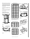
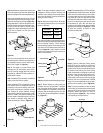
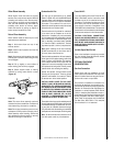
For Canada Only
When installing the chimney system through
an open attic space, the attic shield assembly-
firestop spacer must be used (
Figure 25
). This
installation is required only for use in Canada.
Locking
Tabs
(Lances)
Note: For Canadian installations, all chimney
installed outside the building must be constructed
with galvalume (outer sections only) effective
January 1, 1992. The appropriate model desig-
nations are located in the back of this manual.
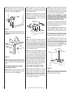
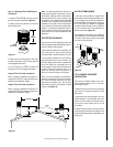
The FTF10 chimney system is a two piece chim-
ney that snap locks together from the fireplace
up. Always start with the inner flue section. With
the lanced end up, snap lock the joint into the
matching collar on top of the fireplace. At all
subsequent joints, the upper flue section fits into
the lower or preceding flue section. Each section
snaps together by means of locking tabs (9 tabs
per joint). Check each section by pulling up
slightly from the top to ensure proper engage-
ment before installing succeeding sections. If
the flue has been installed correctly, it will not
separate when tested. Also, the inner flue joint
where each section is joined should be tight and
flat without gaps (
Figure 26
).
Figure 26
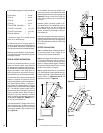
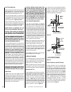
The outer chimney section installs the opposite
way; the lanced end goes down and each new
section installs OVER the outside of the previ-
ous section (
Figure 27
).
Figure 27
Figure 25
Step 4.
Note: All chimney sections are con-
structed with a unique locking tabs and hem
design, which ensures and immediate, tight
assembly between sections. Plan your chimney
requirements carefully before assembly, as the
chimney is difficult to disassemble after instal-
lation. If disassembled, the tabs might become
damaged. Be certain that the tabs are properly
formed to ensure they engage properly.
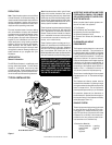
Step 3. Position the appropriate firestop
spacer at the ceiling and nail temporarily with
two (2) 8d nails. Use a flat firestop spacer,
Model F10FS-2, for the FTF10 system if chim-
ney penetrates vertically. If the chimney pen-
etrates through the ceiling at a 30° angle (offset
chimney) then use a 30° firestop spacer, Model
F10FS30-2. Use one nail on opposite sides of
the firestop to hold in position. Nail perma-
nently, using at least two (2) more 8d nails,
after the chimney sections have been assembled
through the firestop spacer and after necessary
adjustments have been made. The firestop
spacer must be secured in place by at least four
(4) 8d nails when completely installed.
Note: If there is a room above the ceiling level,
the firestop spacer must be installed on the
bottom side of the ceiling. If an attic is above the
ceiling level, the firestop spacer must be in-
stalled on the top side of the ceiling joists
(Figures 21 and 22 ).
Open Attic Space