


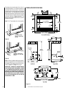
NOTE: DIAGRAMS & ILLUSTRATIONS NOT TO SCALE.
11
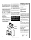
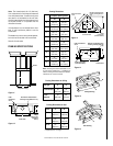
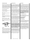
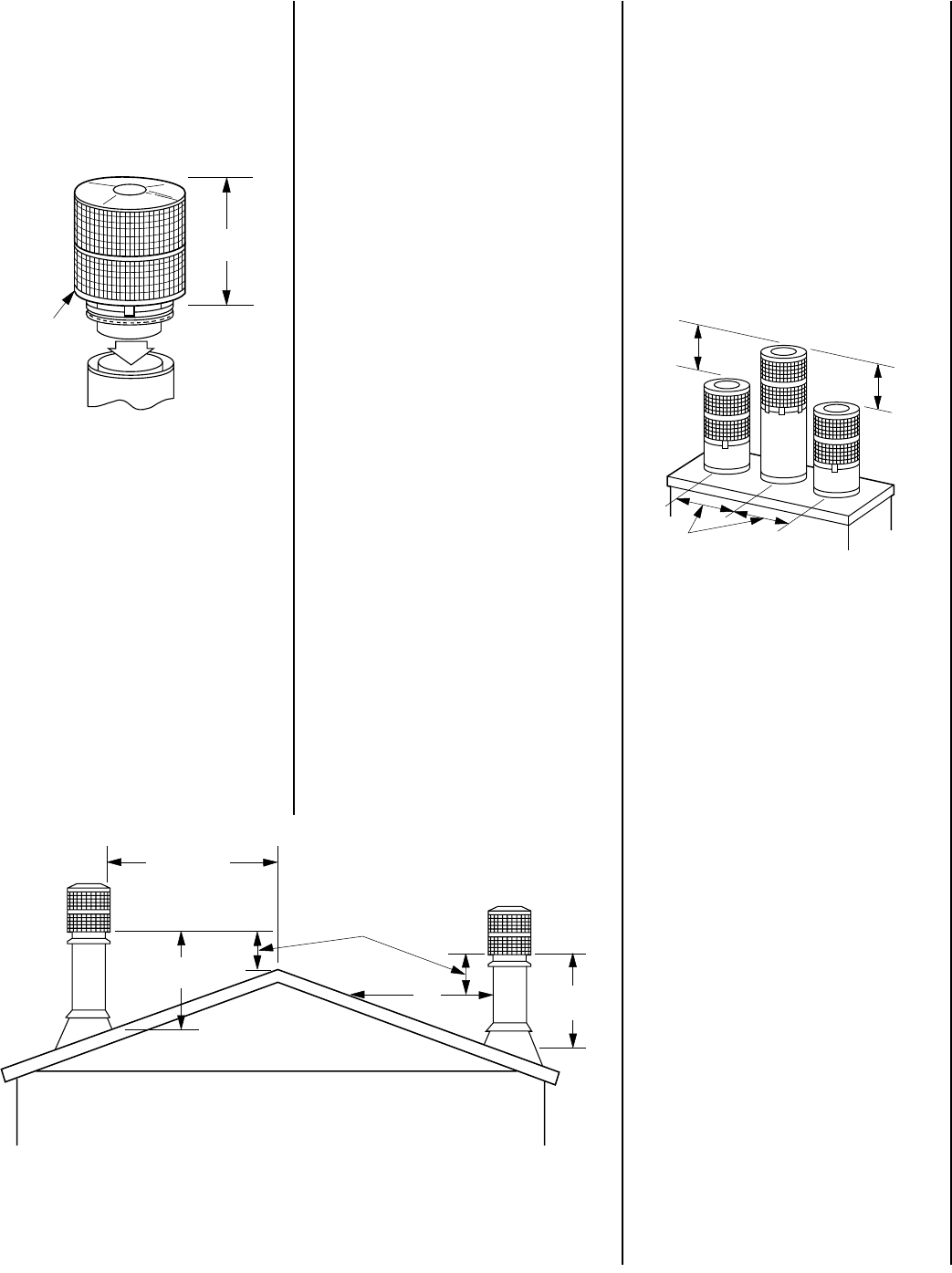
Figure 34
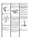
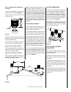
3. Center the outer locking section over outer
flue pipe. Push down until all locking tabs are
firmly engaged and locked.
4. Pull up slightly on CTDTM to ensure the
locking joint is firmly engaged and locked.
Using a FTF10-CT1 Chase Termination:
Refer to specific installation instructions in-
cluded with FTF10-CT1 chase terminations for
clearance and installation details.
Using a FTF10-CT2 Chase Termination:
Refer to specific installation instructions in-
cluded with FTF10-CT2 chase terminations for
clearance and installation details.
Note: It is recommended that all exterior ex-
posed metal fireplace components; such as
terminations, flashings, storm collars and/or
flue be painted with a premium quality, high
temperature, rust preventative paint designed
for metal. This is especially important when
installations are made in abnormally adverse
or corrosive environments; such as near lakes,
oceans or in areas with consistently high hu-
midity conditions. Consult the paint manufac-
turers instructions for proper preparation and
application.
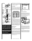
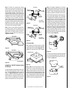
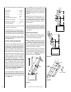
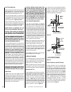
TEN FOOT RULE SUMMARY
The minimum chimney height above the roof
and/or to adjacent walls and buildings is speci-
fied by all major building codes.
If the horizontal distance from the peak of the
roof is less then 10', the top of the chimney
must be at least 2' above the peak of the roof.
If the horizontal distance from the chimney
edge to the peak of the roof is more than 10' a
chimney height reference point is established
on the roof surface 10' horizontally from the
chimney edge. The top of the chimney must be
at least 2' above this reference point. In all
cases, the chimney cannot be less then 3'
above the roof at the edge of the chimney.
The 2' in 10' rule is necessary in the interest of
safety but does not ensure smoke-free opera-
tion. Trees, buildings, adjoining roof lines,
adverse wind conditions, etc., may require a
taller chimney should the fireplace not draft
properly (
see Figure 35
).
Figure 35
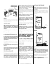
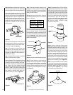
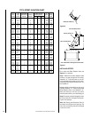
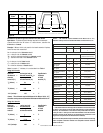
MULTIPLE TERMINATIONS
If more than one termination is located in the
same chase or within the same general proxim-
ity, we suggest they should be separated in
distance at least 24" horizontally from flue cen-
ter to flue center and stacked or staggered
vertically at least 18" apart, from the termina-
tion of one smoke exit to the termination of
another smoke exit (
Figure 36
).
This suggestion is provided in the interest of
better operation. If the terminations are located
too close to each other, smoke may migrate
from one flue into the other.
Figure 36
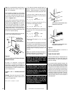
FTF10 CHIMNEY COMPONENT
CALCULATIONS
The minimum installed height of the com-
pleted fireplace system is 15' 0". The maxi-
mum height is 60' 0".
To determine the number of chimney sections
and chimney components required, follow
these steps:
1. Determine total vertical height of the fire-
place installation. This dimension is the dis-
tance from the surface the fireplace sets on
to the point where smoke exits from the
termination.
2. Determine the number of chimney compo-
nents required, except chimney sections. This
would include firestop spacers, stabilizers, roof
flashing, etc.
Step 10. Installing a FTF10 CTDTM Round
Termination:
1. Hold the FTF10 CTDTM over the top of the
last chimney section installed (
Figure 34
).
2. Center the inner slip section into inner flue
pipe and slip down.
20"
(508mm)
CTDTM
Termination
18"
(457mm)
18"
(457mm)
24"
(610mm)
Less Than 10'
3'
Min
2' Min.
10'
3'
Min