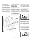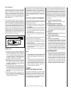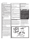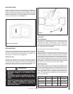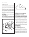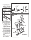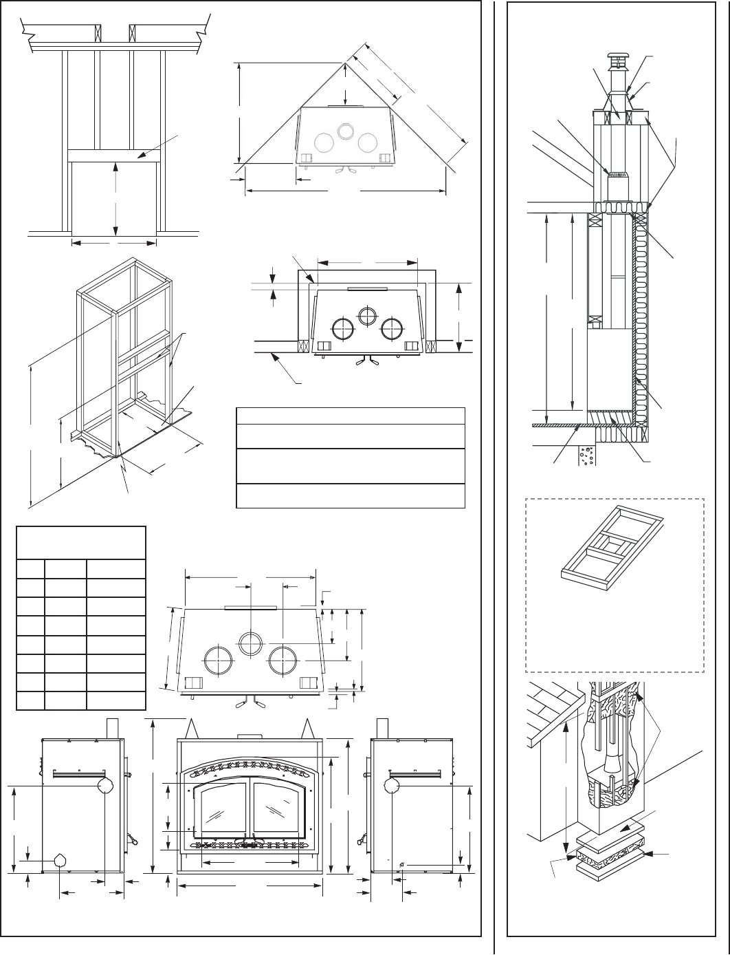
Figure 11
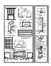
Insulated Chase Construction
7 Ft.
Min.
Attic
Radiation
Shield
Roof Support
Storm
Collar
Flashing
Drywall or
Any Rigid
Material
2” x 4”
1/2” Plywood
6’ 8”
Min.
Firestop
* Floor
Ceiling
Wall
* Floor
Ceiling
Wall
Fireplace
Optional
Insulation
In Outside
Walls Of
Chase
Solid
Continuous
Surface
Outside
Base
Insulation
(Thermal Barrier)
8'
Level
Note: Floor
and wall
below the
attic must
be insulated
using the
same
insulation.
• Must have the same fi restopping
resistance as adjacent wall.
• Must have the same insulation as
adjacent ceiling.
• Follow local rules regarding fram-
ing construction.
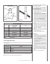
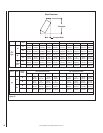
FRAMING DIMENSIONS
Fireplace Opening Width
A 46-3/8” 1178 mm
B 49-1/2” 1257 mm
C 42-3/4” 1086 mm
D 20-7/8” 530 mm
E 93-7/8” 2384 mm
F 47” 1194 mm
G 27-3/4” 705 mm
J 66-3/8” 1686 mm
Notes
Due to Lennox' ongoing commitment to quality, all specifi cations,
ratings and dimensions are subject to change without notice.
All framing dimensions calculated for 1/2" dry wall at the fi replace
face. If sheathing the chase or fi nishing with other thickness materials,
calculations will need to be made.
* Zero inch (0" ) air space to insulation and building materials on
back and sides.
Header
B
A
* Total depth is 25 inches including the
back spacer minus 1/2 inch for drywall
to be fl ush with the facing.
7’
Min.
B
G
A
2” x 3”
Min.
Rough Framing Face
(unfi nished shown)
29-1/2”
23-3/4”
F
D
J
E
7/8”
11-1/8”
16-1/4”
26-1/8”
1”
1-5/32”
26-1/4”
10-1/4”
41-3/4”
49-3/8”
46-1/4”
43-1/4”
37”
31”
15”
7”
4-1/4”
28-1/2”
5-5/8”
20-1/8”
28-1/2”
5-5/8”
10-3/8”
3”
OUTSIDE CHASE
G
C
Back Wall of Chase/Enclosure
Including Finising Materials if any
Rough Framing Face (Unfinished Shown)
Zero
Clearance
CORNER
INSTALLATION
Plywood
Figure 10
NOTE: DIAGRAMS & ILLUSTRATIONS ARE NOT TO SCALE.
9


