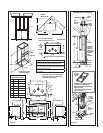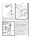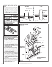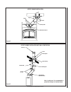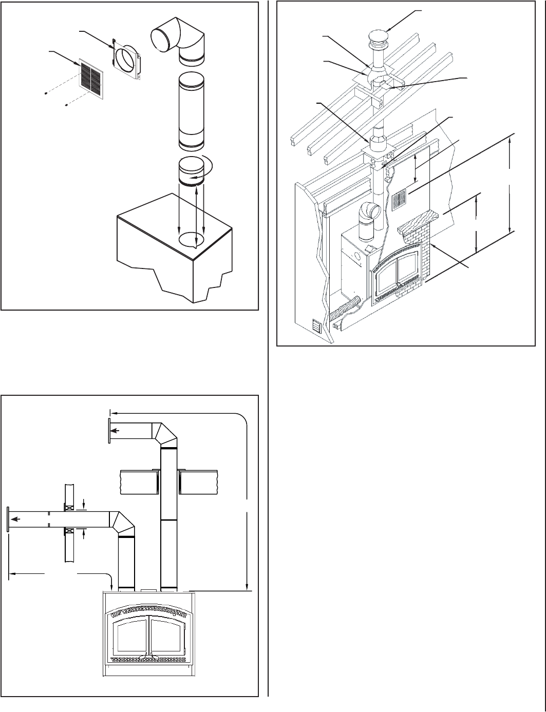
Figure 17
13” x 13”
10’ Max.
10’ Max.
Rain Cap
Flashing
Collar
Flashing
Roof Support
Attic
Radiation
Shield
Non-Combustible
Flameproof
Facing
56” Min.
68” Min.
Figure 18
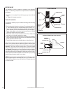
The duct system must be installed respecting the following:
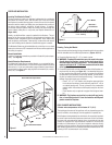
1. Remove the plates closing up the 8” dia. holes on top of the fi replace.
Then, cut the insulation in order to obtain two 8” dia. openings. Fix
the adaptors on the fi replace openings by turning clockwise (Figure
16).
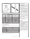
2. Maintain at least a 2” (50 mm) clearance between the ducts and any
combustible material; the required hole size is 13” x 13” (330 mm x
330 mm).
Exception #1: For the grills, the framing can be 10-3/4” x 10-
3/4” (275 mm x 275 mm) to provide the clearance as required
by the integral spacers on the double outlet duct system.
3. The maximum number of elbows in a run of duct is two.
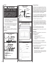
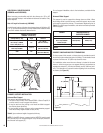
4. Maintain at least 6-1/2” (160 mm) clearance from the outlet grill
framing to a combustible ceiling, side wall or mantel.
5. When traversing a combustible wall or fl oor, a fi restop must be installed
at the wall or fl oor penetration. The hole size must be 13” x 13” (330
mm x 330 mm)
6. Do not connect the hot air ducts to a central heating system. Malfunc-
tion of the heating system’s blower will cause the fi replace to overheat.
A furnace duct is only single wall and not double wall as is required
for the Montecito Estate™ hot air exhaust.
7. Use only Security Chimneys International grills and components as
described in this manual. Other grills or registers may be too restric-
tive and may overheat the fi replace or ceiling.
8. Do not use insulated fl exible ducts as they will overheat.
9. Do not use tees or any other components than the ones specifi cally
listed here.
10. Never allow the ducting to pitch down as hot air will be trapped creat-
ing a fi re hazard. Never route the ducting downwards.
11. The hot air outlet grills must be installed with the louvers pointing
downwards in order to prevent overheating adjacent ceilings.
Figure 16
When installing the double outlet system, the hot air outlets can be
installed in the same room as the fi replace, or one or both of the outlets
can be installed in adjacent or upper rooms. Installing the ducts at dif-
ferent elevations will tend to exhaust more heat out of the higher outlet
(Figure 17).
Frame
Grille
Maintain at least 6-1/2”
(160 mm) clearance from
the outlet grill framing to
a combustible ceiling,
side wall or mantel.
Outlet Grill
Outlet Grill
WARNING: The outlet
grills should not be
installed facing up-
ward through a fl oor.
Danger of burns can
result if grills in fl oor
are stepped on.
6-1/2” Min.
(to ceiling)
Firestop
NOTE: DIAGRAMS & ILLUSTRATIONS ARE NOT TO SCALE.
11


