6
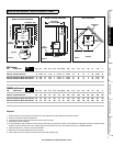
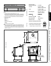
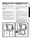
WARNING: BE ABSOLUTELY SURE THE DISTANCE BETWEEN THE
HEATER AND THE SURFACE OF ANY COMBUSTIBLE CONSTRUC-
TION IS NOT LESS THAN SHOWN IN THE FIGURES ON PAGE 7.
Floor Protection
USA - The floor in front and under the heater must be protected with
noncombustible material. The covering must extend 16” in front of the
door opening of the heater and 8” to either side of the door opening.
Canada - The floor in front and under the heater must be protected with
noncombustible material. The covering must extend 457 mm in front of
the door opening of the heater and 200 mm to either side of the stove
body and 200 mm to the rear or to the wall, whichever is smaller.
USA and Canada - A chimney connector / venting extends horizontally
over the floor, protection must also cover the floor under the connector
/ venting and at least 2” (51 mm) to either side.
Alcove Installations USA and Canada - The floor protection must be a
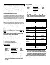
thermally rated non-combustible floor protector. See Page 8 for details
on determining acceptable floor protection materials or hearth pads for
alcove installations.
Alcove Installation
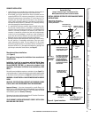
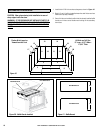
Clearances - In alcove installations, only 6” double wall connector pipe
can be used (single wall or single wall pipe with shield is not allowed).
Minimum alcove width between combustible materials is 52” (1321 mm).
Maximum alcove depth is 48” (1219 mm). Minimum alcove height is
90” (2286 mm).
Thermal Floor Protection - Thermal floor protection is only required
where the stove is installed into an alcove.
Chimney and Connector
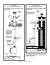
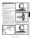
Minimum 6" diameter, minimum 24 MSG black steel connector pipe with
UL103HT listed factory-built chimney suitable for use with solid fuels
or masonry chimney. Horizontal connection not tested, refer to local
building codes for installation. See installation instructions for details.
Restrictions apply! Read instructions before installing.
Residential chimney systems must be from the same brands as listed
for mobile homes but connector pipe may be double wall, single wall, or
single wall with shield as listed.
This appliance may be vented into a code-approved masonry chimney
with flue liner.
WARNING: CHIMNEY CONNECTOR MUST BE IN GOOD CONDITION AND
KEPT CLEAN. DO NOT INSTALL DAMAGED PARTS.
All of the stove connector pipe used must be of the same brand. The
chimney that the stove pipe transitions into may be a different brand.
Other than the transition of the stove pipe into the chimney, do Not mix
different brand vent components. Install all vent components per vent
manufacturer’s instructions.
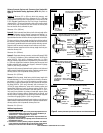
The chimney connector shall not pass through an attic or roof space,
closet or similar concealed space, or a floor, or ceiling. Where passage
through a wall, or partition of combustible construction is desired, the
installation shall conform to CAN/CSA-B365, Installation Code for Solid-
Fuel-Burning Appliances and Equipment.
There must be an effective vapor barrier at the location where the chimney
or other component penetrates to the exterior of the structure. Follow the
vent manufacturer's detailed instructions.
IMPORTANT NOTE: See Draft Requirements and Selecting a Proper
Venting System on Page 4 to assist you in choosing the proper venting
system for your installation.
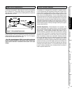
Clearance dimensions are to flue collar. If a single wall connector pipe
with shield is used, a 1 inch air space is needed between pipe and shield.
Shield attaches to rear of stove pipe and must run from stove top to ceil-
ing. Pipe shield shall be UL listed.
Components Required For Installations
Legs OR Pedestal Assembly.
Use all required components specified for this appliance. Do
not substitute.
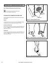
WARNING: In the event that you remove the blower for any
reason, make sure a cover plate (available from Lennox Hearth
Products) is installed before using the heater. Note: The cover
plate is not necessary if a blower has never been installed
because a knock-out will be in place to act as the cover.
CLEARANCES TO COMBUSTIBLES


